If you are a beginner and you want a power supply that the output voltage can be adjusted. Then a variable power supply circuit is what you are looking for. But there are many circuits in this category.
So, I try to compile most of them into this list. That you can choose the most suitable for your usage and learning.
I think we should learn from the transistor circuits first before the IC in order to understand the basics. But if you looking for a circuit suitable for practical use, the IC circuits should be given priority.
What is a variable power supply circuit?
What is a variable power supply? it is a power supply that can adjust the output voltage or current. But it still has the same characteristics as a fixed-regulated circuit. It will keep a stable voltage when it has any load.
For example, you are experimenting with a circuit that requires a 12V power supply, so you are starting to look for a 12V power supply circuit. But you also want to know if it works better with a 15V or 9V power supply.
Surely, it would not be convenient to have 3 power supplies with 9V, 12V, and 15V just for testing. Unless you are a power supply collector like me. LOL
Would it be better if you could do all of that with just one variable power supply? Yes!
Of course, it will keep its main feature is that it maintains the same constant voltage as same as a normal fixed output power supply. For example, when you set the voltage to 9V, it will always stay at a constant 9V no matter how heavy the load is.
17+ Variable Power Supply circuits
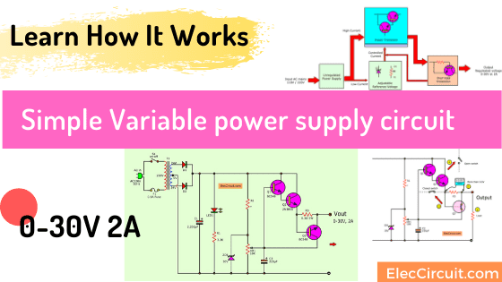
Simple Variable Power Supply Circuit
This circuit can output 0-30V 2A. It may be best suited for you. Because it has a few parts, small in size, and also very cheap.
The features of this handset are the DC voltage continuously from 0-30 volts. And, apply current up to 2 amperes. And can be put easily in a large pro box. The power supply is a circuit that is easy to understand. Because there are quite clear components.
I like to study it. If you like me. Let’s see. Is it really easy to understand?
Learn Block Diagram
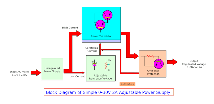
This is a Block Diagram of a Simple Adjustable Power supply circuit. Let me explain to you how it works step by step.
Unregulated Power supply
The unregulated power supply will change the AC main into a lower DC voltage, about 36V 2A. Almost all of the power supply will use it. I believe that you have used it and understand how it works well.
Adjustable Reference Voltage
The electricity is divided in 2 ways.
The first way:
Some little current flows through Adjustable Reference Voltage. It determines the output voltage level of the output constant. This circuit consists of a Zener diode and a variable resistor.
Power Transistors
The Second way:
The most current will flow through the power transistor. It works like a large bridge for higher current through. And it has a controlled current lead. To control the max output current, 2A.
Overload Protection
When the current exceeds 2A. The power transistor is working hard. There is high heat. Until it may be damaged. And also damage other devices.
We should therefore have the overload protection section. Inside there is the resistor to check higher current and the transistor to cut off the controlled current of the power transistor down.
How It Work
First, we apply the AC line to the circuit to SW1 on/off to the transformer T1 and fuse F1 to the protection circuit when there is too much power source. Here is the unregulated power supply(full-wave rectifier) Section.
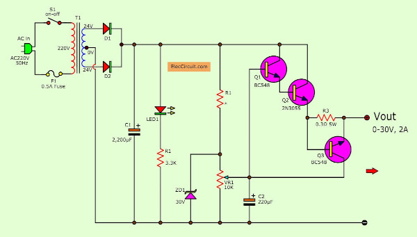
Second, T1 reduces AC voltage 220V into 24V 0 24V, the current through to both diode D1 and D2 to rectifiers to DC voltage. Next, C1 filters current to a DC voltage of about 36VDC and 2A max. There is LED1 to show power on and R1 limits current to a safe value.
The reference voltage
Next, the current comes to the regulated section. R2-100ohms and ZD1-30V are connected together as the 30V steady DC regulators. The variable resistor VR1 is used to adjust the output voltage between 0V to 30V.
What is more? the constant voltage will control the base of the power transistor Q1 and Q2 in Darlington mode. To drive or increase the output current up to 2A.
Short-circuit Protection
The short-circuit protection of this circuit consists of Q3 and R3, and how it works is very simple.
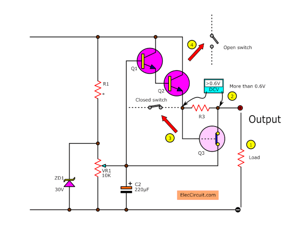
When the load pulls too many currents, as may be the case when there are short-circuits, the voltage across R3 increases to 0.6V, as does the B-E of Q3.
Causing the C-E of Q3 to be like a closed switch and stop the Q1 and Q2 from running, thus cutting off the output to protect the circuit.
Note: In my opinion, this short-circuit protection is not the best, but it is still better than nothing.
How It Builds
The circuit assembly is very simple Because the devices are less Can assemble down on the perforated board. While the power transistor Q3 – 2N3055 is working, will be hot so we always use a heat sink on it. Should use low-wattage soldering iron does not exceed 30 watts. To soldering the legs of transistors and diodes.
Adjustment and Usage
In real usage although it is off, LED power ON will still light up for a moment. Because the LED gets current from C1 that does not discharge fully. If you want to stop LED immediately. You may move R1 and LED1 across the secondary of T1.
Then, add the diode-1N4001 series with the LED to protect voltage backward which LED may be damaged.
Components List
Resistors
R1: 3.3K, 0.25W resistor
R2: 100Ω, 0.5W resistor
R3: 0.3Ω 10W resistor
VR1: 10K Potentiometer
Electrolytic Capacitors
C1: 2,200µF 50V
C2: 220µF 50V
Semiconductors and others
Q1: BD139, 80V 1.5A, TO-225 NPN Transistor
Q2: 2N3055 Power NPN transistor
Q3: BC548,BC549, 45V 100mA NPN Transistor
D1, D2: 1N5402 3A 100V Diode
D3: 1N4002 1A 100V Diode
ZD1: 30V 1W Zener
T1: 117V/230V AC primary to 24V-0-24V,2A secondary transformer
S1: On-Off toggle switch
F1: 110V/220V, 500mA, slow-blow fuse
Be careful with component pinouts
Some components may have an essential pinout that needs to be carefully considered when working with them, which you can check out: Electronic components list with images.
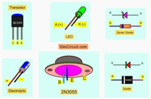
But to be safe, when you come across components you are unfamiliar with, simply look up their specific datasheets.
0-20V Variable Power Supply Circuit Diagram
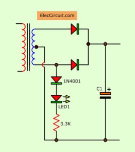
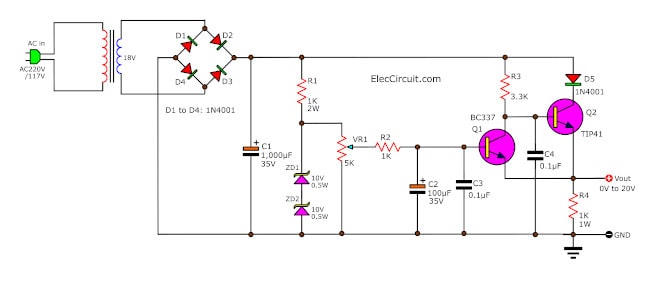
This is a simple 0-20V Variable Power Supply Circuit with a maximum output current of about 1A.
It only uses common components that are easy to buy in any store and uses transistors as the main component and a potentiometer to control the output voltage.
My friend came over one day and brought with him a lot of electronic PCBs. He asked me what to do with them, and I thought that recycling them was a great idea. Since I like doing DC power supply projects, I told him that I would make a 0 to 20V variable power supply with the PCBs he brought over. He also thought that it was a good idea.
How It Works
When the 220V or 120V AC main comes into the circuit, it passes through switch S1 and fuse F1, and then the transformer T1 converts the 220V to 24V. After that, the D1 through D4 rectifier bridge rectifies the AC into pulsating DC. The capacitor C1 acts as a storage capacitor, smoothing up the DC voltage and completing the unregulated power supply part of the circuit.
Now that we have the 24V DC voltage at C1, It then flows through R1 and both Zener diodes, ZD1 and ZD2. Each Zener diode is 10V, so two of them in series will have 20V, which is the reference voltage. The R1 limits current to ZD1 and ZD2 to keep the voltage constant at about 20V.
Next, this voltage comes to the base of the Darlington pair regulator, which consists of Q1 and Q2. Both transistors work together to increase the output current to the load.
Here is a short summary of the purpose of the other components:
- Potentiometer VR1 is used to adjust the output voltage from 0V to 20V.
- Capacitor C2 stabilizes the voltage drop across VR1.
- Both capacitors C3 and C4 reduce noise (transient noise) in a circuit.
- Diode D5 protects a feedback voltage that may harm other components.
The transistors I used here are from recycling the aforementioned PCBs, so if you cannot find these exact models, you may substitute them with TIP41, TIP31, 2SD313, H1061, 2SC1061, MJE3055, or others, as long as they have these key features: NPN transistors with at least 40V/3A.
This 0-20V Variable Power Supply Circuit has an output of 0V to 20V at 1A using a transformer that is rated at 2A. It may drop to 0.7A if you use a transformer that is rated at 1A.
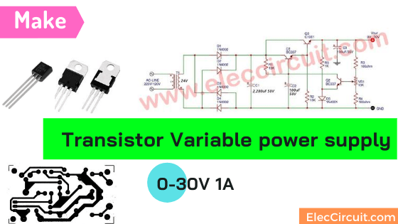
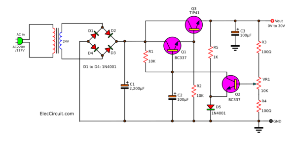
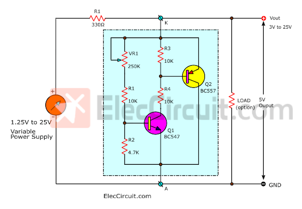
0-30V 1A Transistor Variable Power Supply Circuit
Although this circuit is quite old at this point, it is still interesting because it does not use ICs or Zener diodes and could supply a steady voltage.
How It Works
This circuit’s main components include 2SC1061 and two other small transistors, as well as a few other common components, like the VR1 potentiometer, which is used to adjust the output voltage from 0 to 30V at 1A. Also, because this circuit uses only easy-to-find components, it is suitable for learning the basics of variable regulators.
The IC—integrated circuit—is popular and widely used in these days and ages, as it is smaller, easier, and sometimes cheaper than the alternative. However, there may be a few who still prefer using transistor circuits because of their replaceability and reliability. Whereas replacing a broken IC may be difficult and/or expensive, replacing a single broken transistor inside a transistor circuit is very cheap and simple to do.
First of all, the AC main enters the circuit through the DC unregurated section, which consists of T1, D1, D2, D3, D4, and C1; at this point, the voltage across C1 is about 33VDC. Then, a small amount of current flows through the current-limiting resistor R1 to the base of Q1.
Since Q1 and Q3 are the Darlington-pair emitter-follower, it can greatly amplify current.
Some current from the output flows through R5 to D5, causing the voltage across D5 to be constant at 0.6V.
While a small amount of current flows through the voltage divider circuit, which consists of R3, VR1, and R4.
VR1 adjusts the output voltage by controlling the bias current of the transistor Q2, which in turn controls the bias current of the power transistor Q1. The amount of bias current the Q1 receives will determine the output voltage of the circuit, from 0 to 30V.
The Components List
0.25W Resistors
R1, R2: 10K
R3, R4: 100 ohms
Capacitors
C1: 2,200µF 50V Electrolytic
C2,C3: 100µF 50V Electrolytic
Semiconductors
Q1, Q2: BC337, 50V 800mA NPN Transistor
Q3: 2SC1061 or TIP41 or H1061 or MJE3055, 50V 4A NPN Transistor
D1-D5: 1N4002, 100V 1A Diode
Others
VR1: 10K Potentiometer
T1: 24V 1A transformer
Assembling
First, assemble all the components into the PCB layout below.
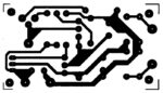
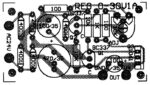
PCB layout of Simple Variable power supply 0-30V 1A
Second, apply the power to the circuit, then use a voltmeter to measure the voltage output.
Third, adjust the VR1; the reading of the meter should change as we adjust it.
Fourth, try connecting the load to the circuit. The output voltage should be a constant voltage.
Do not forget that the Q3 C1061’s hole needs to be lined up properly with the heatsink.
Other reads: The meaning of variable power supply on Wikipedia
The remaining circuits are more advanced or specialized, so in order to keep this article manageable, I decided to create a separate page for each of the circuits listed below. If any of them pique your interest, you can click on the link to learn more about them.
0-30V Power Supply Circuit at 3A
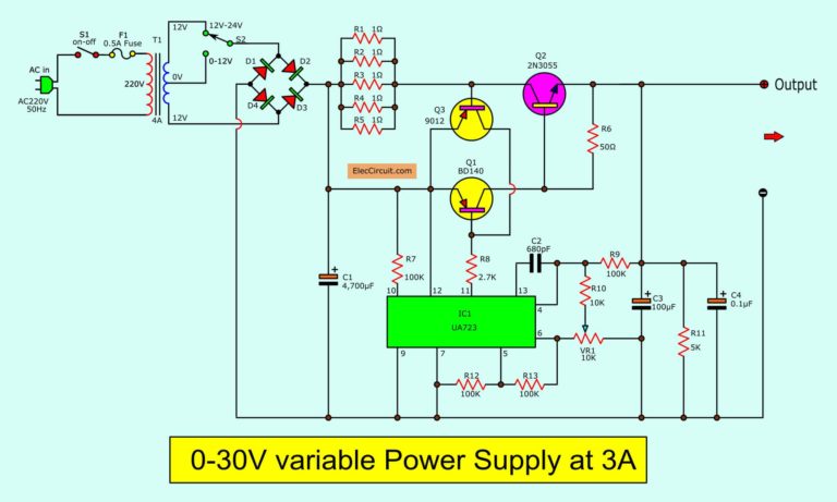
Let’s create a 0-30V 3A Laboratory DC Power Supply. The high-efficiency variable regulator that new circuit design using UA723 and TIP3055.
0-50V Power Supply
Let’s build a 0-50V Variable power supply circuit, 3A. can adjust output 0V to 50V with overcurrent protection at 3 A. Easy Linear supply.
LM317 Power Supply
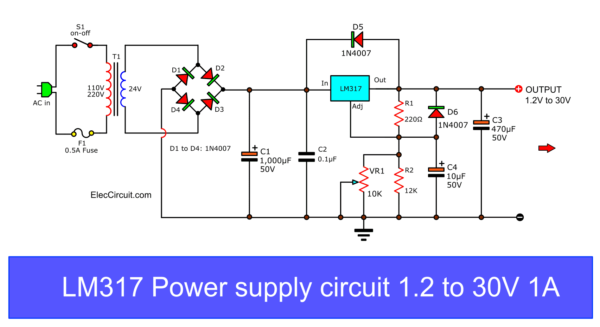
This is First Variable DC Power Supply 1.2V to 30V 1A using LM317. using a few parts and build easy with PCB layout and can fine adjust voltage output.
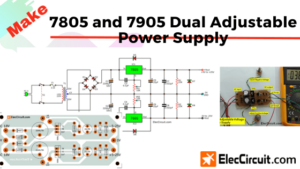
7805 and 7905 Dual Adjustable Power Supply Circuit
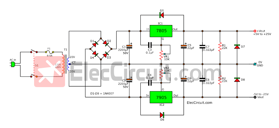
Let’s build an adjustable dual power supply circuit using a 7805 and a 7905 IC. The output can be adjusted from +5V to +25V and -5V to -25V at 1A. It is also a great way to understand the basics of OP-AMP circuits.
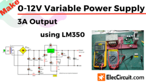
0-12V 3A Variable Power Supply Circuits

In a normal circuit, the general LM350 regulator has a start voltage of 1.25V. But this circuit is special that start of 0-volts. We use only one IC and a few other components. So cheap and easy for you.
LM338 Adjustable Power Supply 5A and 10A
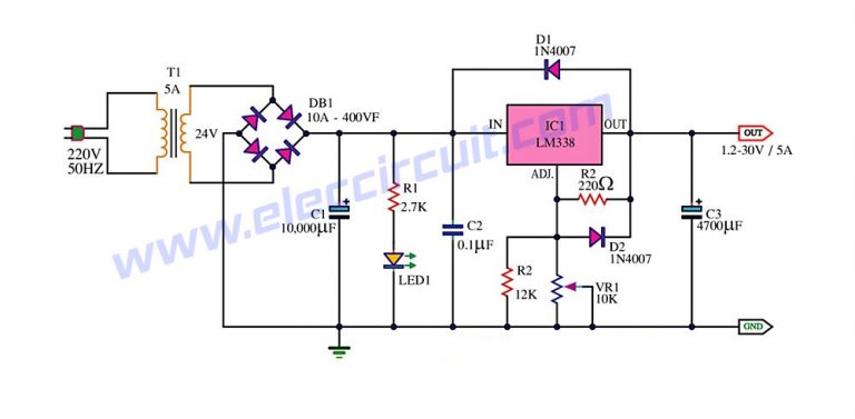
Here is the LM338 Adjustable DC power supply circuit, 1.2V to 30V. It can provide a current maximum to 5A and 10A. They are similar to LM317, so easy to use with a few components. But LM338 has higher a current.
0-30V 20A High Current Adjustable Voltage Regulator Circuit
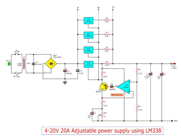
It can give the output current 20A or 400watts and can adjust the voltage of 4 to 20V—or apply to 0 to 30V easily.
LM350 Adjustable Voltage Regulator
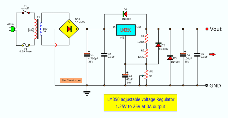
If you need an easy-to-build and good-quality 3A power supply circuit. Many experts often recommend using LM350. It is a 3A voltage regulator IC for DC adjustable power supply(1.25V to 35V), high-performance, with a few components.
LM317 with Pass 2N3055 Transistor Circuit Regulators
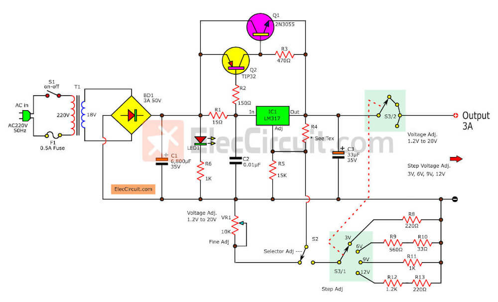
High quality, 3A adjustable voltage regulator. Using LM317 and 2N3055 so easy and cheap. Adjust voltage in steps 3V, 6V, 9V, 12V. And In fine, 1.25V to 20V.
0-60V Dual Variable Power Supply Using LM317&LM337
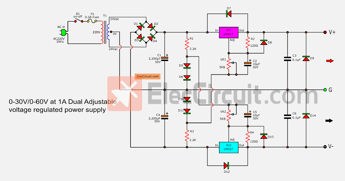
1. On signal mode—can supply DC voltage of 0V to 60V.
2. On Dual rail mode—Can provide DC dual variable on positive, negative and ground, are +/- 0-30 volts.
3. Can supply current out the maximum of about 1.5 A.
Variable Zener Diode Circuit
Let’s make the Zener diode with yourself!
7805 variable voltage regulator circuit with PCB
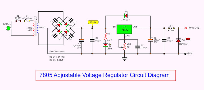
This is IC 7805 adjustable voltage regulator circuit, can adjust voltage output: 5V up to 30V as need 6V,7.5V,8V,9V,10V and 12V etc at 1A it small and cheap[…]
GET UPDATE VIA EMAIL
I always try to make Electronics Learning Easy.
Related Posts

I love electronics. I have been learning about them through creating simple electronic circuits or small projects. And now I am also having my children do the same. Nevertheless, I hope you found the experiences we shared on this site useful and fulfilling.
Thanks.
Hi, Salim Khan
Thanks for your feedback.
You are welcome.
Very interesting !
Hello, Augusto Principato
Thanks for your feedback.
simply—–the best!
Hello, walter
Thanks for your feedback.
Hi, Augusto Principato
Thanks for your feedback.
Hi, walter
Thanks for your feedback.
where is the placement of VR1 10k pot. I can not see it in figure
Hi, subodh
Thanks for your feedback.
Please look at the figure 1.
VR1-10K ,
hi is this still uselful with 12 0 12 volts transformer?? can u make using 12 0 12 volt transformer.?
#Variable power supply 1A, 0-30V
Will it work too for a tranformer that gives a current of 2 Amps? Asap. Thanks 😀
hi, how can i change the output to 3 Amp in this schematic diagram?
This circuit is great. It works. Thanks!
Hey! Plz explain me! How the current is amplified … Coz , its confusing me! Make it fast, or reply to my mail id. [email protected]
#Variable power supply 1A, 0-30V
Hi Van Boni..Yes The Transformer will Take The Current it will need!!! You will then have a 2-1 or 1A of Headroom
#0-20V Variable power supply circuit
What volts of capacitor is the 1000 micro farad? Answer me please.
#0-20V Variable power supply circuit
Capacitors comes in different voltage values in 1000uf capacitance, say like 1000uf,16v , 1000uf 36v , ……..upto 250v I’ve seen till now . They may be available more than 250V also!.
#0-20V Variable power supply circuit
Here the maximum voltage is 24 v as per the transformer output so you can use capacitor voltage value more than 24v. (The voltage mentioned on the capacitor means the maximum voltage that capacitor can bear)
Hiii
I would like to send me some mini circuits
Hello, Mamdouh
If you still want mini circuits. I will send you the email. Thanks
a current limit function would be very nice..anyone can tell me how to add a current limiter function to this circuit?
Hello, Jed Frances Ararao
Thanks to your question. This is a simple circuit. It has basically a current limiting function. When the current is too much. There is a voltage across R3. Then, Q3 get a biased current. It works, the collector and emitter is low voltage. Thus, Q1 and Q2 stop. No current to load.
Is it possible to change the output current to 1.5 A with small adjustments? And which are they?
Hi,
Yes, you can use for 1.5A output when using 2A transformer.
If the output current is always dependent on transformer secondary,
then what is the usefulness of the output transistors
Hi Andrew,
The output transistor work looks like a big bridge for a lot current through.
Join the discussion…ok thank u, but can u please explain further, more about how it look like a bridge, or like an analogy or illustration
Hi,
Thanks for your feedback.
I updated this article. It will be helped you understand more.
#Variable power supply 1A, 0-30V
May I ask what is the secondary rating of the transformer?
Hello Mahar Falcutila,
Thank you for visiting and interested in this project.
It is 24V 1A transformer.
If your project is successful. Don’t forget to share it with me, thank you.
Thank you for such an amazing explanation/tutorial!
I only have one question. When connecting the transformer outputs in parallel, the voltage would be 24V, not 48V! Why does the diagram shows such connection? Shouldn’t the transformer be in series to output 48V? Thanks for your response 🙂
Hello Victor G.
Thanks for your feedback. I am happy that you interested in this circuit.
It is a full-wave rectifier unregulated power supply circuit mode.
Yes, you are correct. My drawing is wrong. You are a great person.
Thanks a lot back.
Apichet.
Hi, kindly show me the correct drawing , i wannted to make a variable power supply of 0-30v and 2A current maximum.. i am a beginner and a bit confused that in book LM317 IC is used …can we make this circuit by using transistors?
Hello wasay,
Thanks for your question. I am happy that you are interested in Electronics. Yes, when you are a beginner it has a lot of information. But you need to know. Do not worry about mistakes. It may be a step toward good learning.
This circuit is easy to build. But my experience. It might not be the best circuit for us. It is better If you have tried to build many circuits.
Have a good day.
Can you provide the DC output spectrum of this circuit shown by CRO?
thanks
in first circuit with Q1 Bc547 : Q1 go hot.
& replace with BD139.
Thanks for helping.
It is a good idea.