The Simple Solar Plant Watering Alarm Circuit we have learned about before does not actually water the plant for us. Wouldn’t it be better if we integrated the watering system into it? And that is what we are going to do in this Small Automatic Plant Watering with a Solar Cell Power System.
In building this circuit, we will get a chance to learn about other levels of electronics, namely the LM311 comparator and NE555 timer. These components help increase the efficiency of the circuit; however, the idea behind the circuit remains the same, which is the use of easily accessible and low-cost components.
Circuit Design and Choosing Components
So now, let’s pick our components and design the circuit.
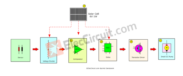
Block Diagram Automatic Plant Watering
Start with creating the block diagram of this circuit, which contains general ideas about the circuit and helps us design it more effectively.
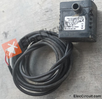
The Small DC pump
Starting with the pump, we already have a small 5V to 12V DC pump that requires about 200mA of current. However, it only consumes 200mA of current during its startup process; after that, it needs about 180mA.
The Solar Cell
So if we were to use the 6V 1W solar cell as before, the pump would not work because the current is insufficient and the voltage would drop to just around 2V.
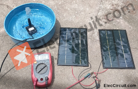
Then we try using a solar cell with a higher current of 100mA at 9V 1W. However, the current remains too low for the pump to function. We thus connected another same-spec solar cell in parallel with the old one, which brings the output current to about 200mA. When we connect it to the pump, it works properly; the pump draws around 180mA, causing the voltage to drop to approximately 8V.
The Delay
It might be worth extending the watering time to ensure that all of the soil in the pot receives adequate water. Because, without the timer, the pump will simply stop working once the soil surrounding the sensor becomes sufficiently moist.
So we should increase the time to 30 seconds with a NE555 timer chip, which is simpler and more accurate than the previous delay timer with a transistor and a capacitor we used before.
.
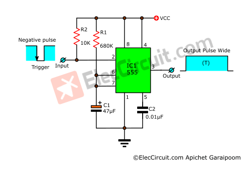
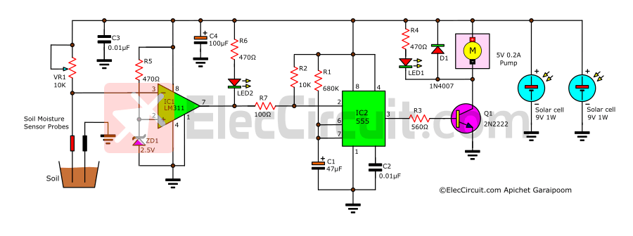
As shown in the circuit above, it is a simple delay circuit using a 555 timer in monostable mode. The 555 timer will deliver a positive output pulse called output pulse width (T) only if its pin 2 detects the negative trigger pulse in a falling edge form.
R1 and C1 control the length of this time delay.
We can easily calculate the output pulse width (T) using the formula:
T = 1.1 × R1 × C1
We already know that the duration (T) is 30 seconds. As for the rest, we will start with C1, in which we will choose a 47uF 25V one. Next is R1, and since we already picked C1, we can easily calculate the value of R1 by converting the formula to:
R1 = T ÷ (1.1 × C1)
Substitute the value:
R1 = 30S ÷ (1.1 × 47uF)
R1 = 580,270Ω
But we are going to use 680K instead.
Anyhow, if the value of R1 exceeds 2M, there will be a greater time fluctuation.
The Transistor Driver
Theoretically speaking, the NE555 could power a maximum of 200mA of load. But in actual usage, we should use a transistor to drive the pump instead.
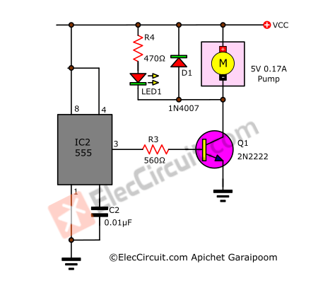
The transistor we chose as a driver transistor is PN2222, with the following specifications: IC max = 600mA, VCE max = 30, hFE gain min = 30.
How to find the value of R3
We can find the value of R3 easily with this formula.
R3 = (Vpin3 – VBE) ÷ IB
And what we already know:
The VBE of the transistor is 0.7V.
The Vpin of 555 is around 0.6 times the VCC; since the VCC is 8V, Vpin 3 is thus equal to 4.8V (8V × 0.6).
The IB of the transistor is equal to IC ÷ hFE. Where IC is the pump’s current, 180mA. And the hFE is 30, down from 50 because of the high current.
Therefore, IB = 180mA ÷ 30 = 6mA
Substitute the formula above.
R3 = (4.8V – 0.7V) ÷ 6mA
R3 = 683Ω
We will be using 560Ω for R3.
The Comparator
We need our moisture detection to be as accurate as possible, so instead of a transistor circuit, we will be using the LM311 voltage comparator IC. It has the same DIP-8 as the 741 chip but with a higher efficiency.
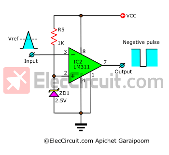
Since we want a negative pulse to trigger the 555 timer, we would need to set the LM311 to ‘inverting comparator’ mode.
The current flows through R5 and ZD1, causing pin 2 (the non-inverting input) of the IC to remain at 2.5V, a reference voltage (Vref).
In normal conditions, the input voltage (Vin) will be lower than Vref, which causes the output to have a high voltage. However, when the Vin is higher than the Vref, the output will instead switch to a ‘low’ state.
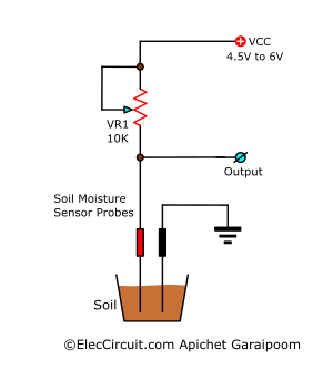
The Sensor and Voltage Divider
Next are the sensor and voltage-divider parts of the circuit. We are still going to use the soil moisture level as a measuring factor.
Note: Since we have already covered this part of the circuit in the previous article, for the sake of simplicity, I recommend you read it first here: The Sensor
The sensor probes are composed of two pieces of conductive metal staked into the soil; the resistance between the two probes indicates the moisture level of the soil. It is combined with VR1 to be a voltage divider circuit that outputs to the OP-AMP the voltage it needs.
Then, if we bring every part together, we can assemble it into the Small Automatic Plant Watering circuit with a Solar Cell Power System, as shown below.
Building this circuit
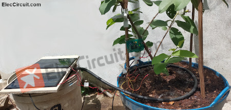
We assemble this circuit on a perforated PCB, making it small and quite quick to build.
After finishing assembling the circuit and rechecking everything, we will try putting the circuit to real use. First, use the VR1 to adjust the sensitivity of the sensor until the LED2 lights up, which shows that the soil is dry; you may have to adjust the distance between the two probes as well. The LED1 will then illuminate, indicating that the pump has begun to operate and, as a result, the moisture level has increased.
As the soil moisture level goes up, you may see that the LED2 goes out; however, the LED1 is still on, as is the pump. And if both the pump and the LED1 remain on for another 30 seconds, it means that the circuit is fully functional. If your soil has not been watered sufficiently within 30 seconds, you can adjust the values of C1 and R1 to further extend the watering time.
Conclusion
We have been using this circuit for a couple of months now, and it has been working quite well. It helps to conserve water and water the plant properly. However, this circuit still has a downside: during a day with a low amount of sunlight, the circuit may not have worked at its maximum potential. As a result, we should include a battery, which we plan to improve in the future.
GET UPDATE VIA EMAIL
I always try to make Electronics Learning Easy.
Related Posts


I love electronics. I have been learning about them through creating simple electronic circuits or small projects. And now I am also having my children do the same. Nevertheless, I hope you found the experiences we shared on this site useful and fulfilling.
Great article.
Thanks 🙂