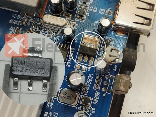
We notice that newer circuit boards that use SMD components often have an AMS1117 voltage regulator IC.
Its key feature is that it is a low-drop regulator, which means that it reaches its maximum efficiency with an input voltage that only needs to be a little bit higher than the output voltage, or around 0.9V to 1.2V.
For example, if the load requires 3.3V, we can just supply it with an input voltage of around 4.5V to 5V. It can also supply a current of up to 1A, despite being small and economical.
Features of AMS1117
The fixed voltage regulator version of this chip has a wide range of voltages to choose from, which are 1.2V, 1.5V, 1.8V, 2.5V, 3.3V, and 5V.
- AMS1117-1.2 for 1.2V output
- AMS1117-1.5 for 1.5V output
- AMS1117-1.8 for 1.8V output
- AMS1117-2.5 for 2.5V output
- AMS1117-3.3 for 3.3V output
- AMS1117-5.0 for 5V output
The output accuracy is also at 1.5%, similar to the 78xx regulator IC series.
There is also a version with adjustable output voltage, so if we want 4.5V of output, we can choose the AMS1117-ADJ. Its starting voltage is 1.25V, similar to LM317.
The maximum input voltage is 20V with a recommended 15V.
It is a low-dropout regulator (LDO regulator), meaning that its voltage dropout is just about 1.2V at a current of 1A. However, if the load current is lower than 1A, such as 10mA to 50mA, the voltage dropout will drop further to about 0.9V.
It has a current-limiting system at the output when the current exceeds 1A, a thermal shutdown when the temperature gets too high, and a wide operating temperature range of -40 °C to 125 °C.
Application
It can be used in a wide range of applications, as stated in the datasheet. For example in Laptop, Palmtop, Laptop, and Computers, Battery Powered Systems, Battery Charger, SCSI-II Active Terminator, Cellular Phones, Cordless Telephones, Portable Instrumentation, SMPS Post-Regulator, etc.
AMS1117 Pinout
Its commonly found forms can be summarized as follows: TO-252 is generally more durable and can withstand the highest currents for the longest time; on the other hand, SOT-89 is very small and thus suitable for use in a small circuit.
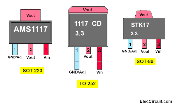
But today we are going to be using the SOT-223 because of its small size and suitability for use in a small circuit that requires a current lower than 500mA.
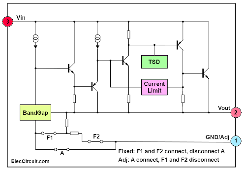
Internal Diagram of the AMS1117
From this simplified version of the internal diagram of the AMS1117, we can see that it is quite similar to the LM317, which is why the Iadj and the Vred are identical.
AMS1117 Fixed Voltage Regulator Circuits
Now let’s look into some sample circuits.
5V to 3.3V Regulator Circuit
The information provided by ESP, the manufacturer of the ESP8266, recommends having 3.0-3.6V of excess voltage. But since the power source we have only supplies 5V, it would not work.
If we were to use the LM317L, it would not work either, because it requires up to 5.8V.
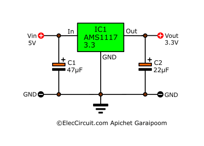
Instead, we chose the AMS1117-3.3. The fact that it is a low-dropout regulator (LDO regulator) allows it to only take 1V to run, or 1.2V in case you need the full 1A current.
C1 and C2 help filter the current to reduce the ripple voltage. The capacitance of C2 should be around 10μF to 22μF; anything more than this would not help.
6V to 5V Regulator Circuit
Here is another interesting circuit. If you have a 6V battery but want to power the digital circuit, which requires a fixed 5V voltage only, you can use this IC (AMS117-5.0) as shown in the circuit diagram.
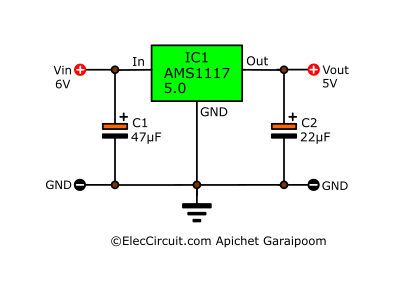
In cases where you want a different voltage level, you can just choose the appropriate one for that voltage level.
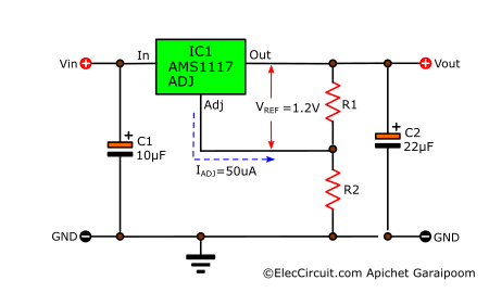
The AMS1117 Adjustable Voltage Regulator Circuits
However, if we want a voltage level other than the fixed regulator version—such as 3V, 4.5V, 7.5V, 8V, 9V, 10V, or other within 12V—we would need to switch to the adjustable regulator version and add R1 and R2 as shown below.
AMS1117 Calculator
As you might have noticed, the circuit layout is quite similar to the LM317 we used to. And calculating the values of R1 and R2 is also not hard at all.
Vout = Vref × (1 + R2 ÷ R1) + Iadj × R2
Where Vref = 1.25V, Iadj = 50μA
Since the value of the Iadj is very low, we might as well simplify that part of the formula, leaving us with:
Vout = 1.25V × (1 + R2 ÷ R1)
So suppose that your R1 is 150Ω and your R2 is 390Ω. You can plug in those values and calculate the Vout, which is 4.50V.
Vout = 1.25V × (1 + 390Ω ÷ 150Ω)
Vout = 4.5V
Or you can use the calculator below to calculate the output voltage.
Next, let’s look at an example of using the AMS1117-ADJ in the power supply circuit below.
6V to 4.5V Regulator Circuit
If we want to supply 4.5V without using three 1.5V batteries, we can use 150Ω for R1 and 390Ω for R2, then inputting a 6V battery to the circuit will result in the desired output of 4.5V.
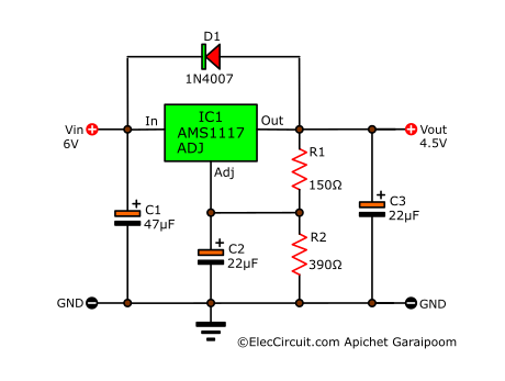
We added C2 (22μF) to reduce the noise, which helps the output voltage be as stable as possible.
And we also added the D1, which acts as reverse-bias protection. Sometimes, the input voltage may suddenly decrease, which can cause some voltage to flow back to the chip and damage it. That’s why we added the D1 to allow this voltage to bypass the AMS1117.
If we need other voltage levels, we can try changing R1 and R2 according to the list below.
A List of Output Voltages with the Corresponding R1 and R2
1.43V : R1 = 470Ω, R2 = 68Ω
1.47V : R1 = 470Ω, R2 = 82Ω
1.47V : R1 = 390Ω, R2 = 68Ω
1.51V : R1 = 330Ω, R2 = 68Ω
1.51V : R1 = 390Ω, R2 = 82Ω
1.52V : R1 = 470Ω, R2 = 100Ω
1.53V : R1 = 390Ω, R2 = 82Ω
1.56V : R1 = 330Ω, R2 = 82Ω
1.57V : R1 = 270Ω, R2 = 68Ω
1.57V : R1 = 470Ω, R2 = 120Ω
1.57V : R1 = 390Ω, R2 = 100Ω
1.59V : R1 = 390Ω, R2 = 100Ω
1.60V : R1 = 240Ω, R2 = 68Ω
1.63V : R1 = 330Ω, R2 = 100Ω
1.63V : R1 = 270Ω, R2 = 82Ω
1.64V : R1 = 390Ω, R2 = 120Ω
1.64V : R1 = 220Ω, R2 = 68Ω
1.65V : R1 = 470Ω, R2 = 150Ω
1.66V : R1 = 390Ω, R2 = 120Ω
1.68V : R1 = 240Ω, R2 = 82Ω
1.71V : R1 = 330Ω, R2 = 120Ω
1.71V : R1 = 270Ω, R2 = 100Ω
1.72V : R1 = 220Ω, R2 = 82Ω
1.72V : R1 = 180Ω, R2 = 68Ω
1.73V : R1 = 470Ω, R2 = 180Ω
1.73V : R1 = 390Ω, R2 = 150Ω
1.76V : R1 = 390Ω, R2 = 150Ω
1.77V : R1 = 240Ω, R2 = 100Ω
1.81V : R1 = 270Ω, R2 = 120Ω
1.82V : R1 = 150Ω, R2 = 68Ω
1.82V : R1 = 330Ω, R2 = 150Ω
1.82V : R1 = 180Ω, R2 = 82Ω
1.83V : R1 = 390Ω, R2 = 180Ω
1.84V : R1 = 470Ω, R2 = 220Ω
1.86V : R1 = 390Ω, R2 = 180Ω
1.88V : R1 = 240Ω, R2 = 120Ω
1.89V : R1 = 470Ω, R2 = 240Ω
1.93V : R1 = 330Ω, R2 = 180Ω
1.93V : R1 = 150Ω, R2 = 82Ω
1.94V : R1 = 270Ω, R2 = 150Ω
1.96V : R1 = 390Ω, R2 = 220Ω
1.97V : R1 = 470Ω, R2 = 270Ω
1.99V : R1 = 390Ω, R2 = 220Ω
2.02V : R1 = 390Ω, R2 = 240Ω
2.03V : R1 = 240Ω, R2 = 150Ω
2.06V : R1 = 390Ω, R2 = 240Ω
2.08V : R1 = 330Ω, R2 = 220Ω
2.10V : R1 = 220Ω, R2 = 150Ω
2.12V : R1 = 390Ω, R2 = 270Ω
2.13V : R1 = 470Ω, R2 = 330Ω
2.16V : R1 = 330Ω, R2 = 240Ω
2.16V : R1 = 390Ω, R2 = 270Ω
2.19V : R1 = 240Ω, R2 = 180Ω
2.23V : R1 = 470Ω, R2 = 390Ω
2.25V : R1 = 150Ω, R2 = 120Ω
2.27V : R1 = 270Ω, R2 = 220Ω
2.27V : R1 = 330Ω, R2 = 270Ω
2.29V : R1 = 470Ω, R2 = 390Ω
2.29V : R1 = 180Ω, R2 = 150Ω
2.31V : R1 = 390Ω, R2 = 330Ω
2.36V : R1 = 270Ω, R2 = 240Ω
2.37V : R1 = 390Ω, R2 = 330Ω
2.40V : R1 = 240Ω, R2 = 220Ω
2.44V : R1 = 390Ω, R2 = 390Ω
2.50V : R1 = 470Ω, R2 = 470Ω
2.57V : R1 = 390Ω, R2 = 390Ω
2.61V : R1 = 220Ω, R2 = 240Ω
2.65V : R1 = 330Ω, R2 = 390Ω
2.66V : R1 = 240Ω, R2 = 270Ω
2.73V : R1 = 330Ω, R2 = 390Ω
2.74V : R1 = 470Ω, R2 = 560Ω
2.75V : R1 = 150Ω, R2 = 180Ω
2.76V : R1 = 390Ω, R2 = 470Ω
2.78V : R1 = 270Ω, R2 = 330Ω
2.78V : R1 = 220Ω, R2 = 270Ω
2.84V : R1 = 390Ω, R2 = 470Ω
2.92V : R1 = 180Ω, R2 = 240Ω
2.96V : R1 = 270Ω, R2 = 390Ω
2.97V : R1 = 240Ω, R2 = 330Ω
3.03V : R1 = 330Ω, R2 = 470Ω
3.05V : R1 = 390Ω, R2 = 560Ω
3.06V : R1 = 270Ω, R2 = 390Ω
3.06V : R1 = 470Ω, R2 = 680Ω
3.08V : R1 = 150Ω, R2 = 220Ω
3.13V : R1 = 220Ω, R2 = 330Ω
3.14V : R1 = 390Ω, R2 = 560Ω
3.18V : R1 = 240Ω, R2 = 390Ω
3.25V : R1 = 150Ω, R2 = 240Ω
3.28V : R1 = 240Ω, R2 = 390Ω
3.37V : R1 = 330Ω, R2 = 560Ω
3.43V : R1 = 270Ω, R2 = 470Ω
3.43V : R1 = 390Ω, R2 = 680Ω
3.43V : R1 = 470Ω, R2 = 820Ω
3.47V : R1 = 220Ω, R2 = 390Ω
3.50V : R1 = 150Ω, R2 = 270Ω
3.54V : R1 = 180Ω, R2 = 330Ω
3.55V : R1 = 390Ω, R2 = 680Ω
3.70V : R1 = 240Ω, R2 = 470Ω
3.82V : R1 = 180Ω, R2 = 390Ω
3.83V : R1 = 330Ω, R2 = 680Ω
3.84V : R1 = 270Ω, R2 = 560Ω
3.88V : R1 = 390Ω, R2 = 820Ω
3.91V : R1 = 470Ω, R2 = 1K
3.92V : R1 = 220Ω, R2 = 470Ω
3.96V : R1 = 180Ω, R2 = 390Ω
4.00V : R1 = 150Ω, R2 = 330Ω
4.02V : R1 = 390Ω, R2 = 820Ω
4.17V : R1 = 240Ω, R2 = 560Ω
4.33V : R1 = 150Ω, R2 = 390Ω
4.36V : R1 = 330Ω, R2 = 820Ω
4.40V : R1 = 270Ω, R2 = 680Ω
4.43V : R1 = 220Ω, R2 = 560Ω
4.44V : R1 = 470Ω, R2 = 1.2K
4.46V : R1 = 390Ω, R2 = 1K
4.50V : R1 = 150Ω, R2 = 390Ω
4.51V : R1 = 180Ω, R2 = 470Ω
4.63V : R1 = 390Ω, R2 = 1K
4.79V : R1 = 240Ω, R2 = 680Ω
5.04V : R1 = 330Ω, R2 = 1K
5.05V : R1 = 270Ω, R2 = 820Ω
5.10V : R1 = 390Ω, R2 = 1.2K
5.11V : R1 = 220Ω, R2 = 680Ω
5.14V : R1 = 180Ω, R2 = 560Ω
5.17V : R1 = 150Ω, R2 = 470Ω
5.24V : R1 = 470Ω, R2 = 1.5K
5.30V : R1 = 390Ω, R2 = 1.2K
5.52V : R1 = 240Ω, R2 = 820Ω
5.80V : R1 = 330Ω, R2 = 1.2K
5.88V : R1 = 270Ω, R2 = 1K
5.91V : R1 = 220Ω, R2 = 820Ω
5.92V : R1 = 150Ω, R2 = 560Ω
5.97V : R1 = 180Ω, R2 = 680Ω
6.04V : R1 = 470Ω, R2 = 1.8K
6.06V : R1 = 390Ω, R2 = 1.5K
6.32V : R1 = 390Ω, R2 = 1.5K
6.46V : R1 = 240Ω, R2 = 1K
6.81V : R1 = 270Ω, R2 = 1.2K
6.92V : R1 = 150Ω, R2 = 680Ω
6.93V : R1 = 330Ω, R2 = 1.5K
6.94V : R1 = 180Ω, R2 = 820Ω
7.02V : R1 = 390Ω, R2 = 1.8K
7.10V : R1 = 470Ω, R2 = 2.2K
7.33V : R1 = 390Ω, R2 = 1.8K
7.50V : R1 = 240Ω, R2 = 1.2K
8.07V : R1 = 330Ω, R2 = 1.8K
8.08V : R1 = 150Ω, R2 = 820Ω
8.19V : R1 = 270Ω, R2 = 1.5K
8.30V : R1 = 390Ω, R2 = 2.2K
8.43V : R1 = 470Ω, R2 = 2.7K
8.68V : R1 = 390Ω, R2 = 2.2K
9.06V : R1 = 240Ω, R2 = 1.5K
9.58V : R1 = 330Ω, R2 = 2.2K
9.77V : R1 = 220Ω, R2 = 1.5K
9.90V : R1 = 390Ω, R2 = 2.7K
10.03V : R1 = 470Ω, R2 = 3.3K
10.37V : R1 = 390Ω, R2 = 2.7K
10.63V : R1 = 240Ω, R2 = 1.8K
Adjustable 1.2V to 12V Regulator Circuit Using AMS1117
Or we can just replace the R2 with a potentiometer so that we can adjust the output voltage on the fly without having to change the resistor combination.
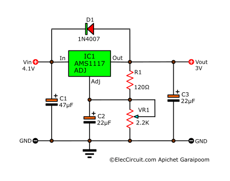
The C2 will improve ripple rejection. The VR1 can be used from 1K to 2.2K for 12V output voltage.
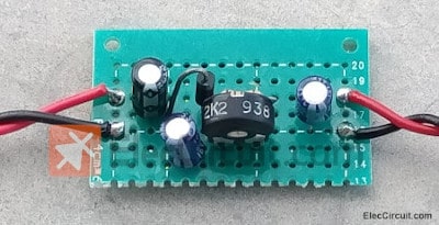
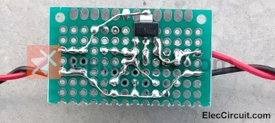
Assembling the Circuit
This circuit only uses a few components, so we will be assembling it on a preferred PCB.
Trying Out the Circuit
We tried using it with a finger pulse oximeter, and it worked exceptionally well. By receiving an input from a lithium-ion battery with a voltage of 4V and the oximeter itself being a load.
Normally, the oximeter requires two AA batteries to operate, which means that it needs 3V. But when we try using two 1.2V Ni-HM batteries instead of non-rechargeable AA batteries, it does not work.
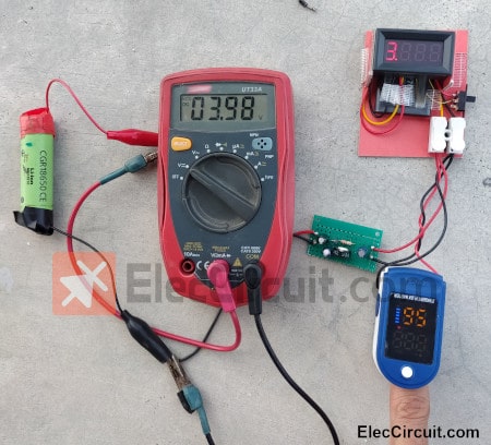
So we switch to using a regulator circuit. Now we just set the output of the regulator circuit to 3V and power the oximeter, which only requires a current of about 30mA to 50mA. This also helps us avoid using a non-rechargeable battery.
Conclusion
We did some experimenting with building a DC regulator circuit using AMS1117, and it generally works well for its size, suitable for a load that requires a low current below 700mA and an input voltage within 12V.
GET UPDATE VIA EMAIL
I always try to make Electronics Learning Easy.
Related Posts

I love electronics. I have been learning about them through creating simple electronic circuits or small projects. And now I am also having my children do the same. Nevertheless, I hope you found the experiences we shared on this site useful and fulfilling.