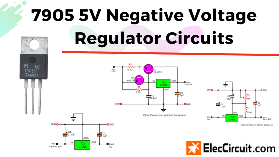
When it comes to a 5V negative voltage regulator, we usually choose the 7905 three-terminal negative regulator chip as the first choice because it is both easy to use and cheap.
Plus, it can supply up to 1.5A when equipped with a sufficient heatsink. We can also turn it into an adjustable voltage regulator by simply adding a potentiometer, or even increase the output current to more than 4A by simply adding a single 2N3055.
7905 Pinout and Specifications
It has a different pin position than the 7805 positive regulator chip, so extra care should be taken.
Buy 7905 at Amazon.com
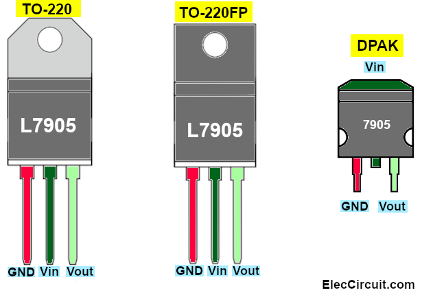
Normally we use it mainly in the TO-220 package, but sometimes we see it in the TO-220FP (plastic body) package and the DPAK package in SMD format as well.
Here is the internal schematic diagram of the 7905.
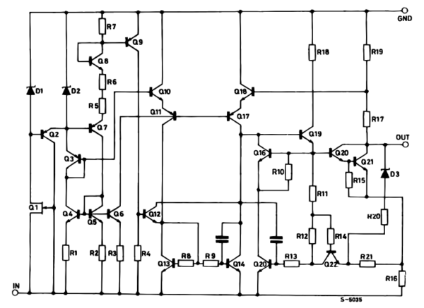
It consists of many components, especially transistors, which greatly help it have higher efficiency than a normal transistor regulator circuit.
7905 Specifications At 25°C
- Output voltage: 5v ± 0.25V
- Input voltage (minimum to maintain line regulation): 7.3V
- Dropout voltage: 2V
- Peak output current: 2.2A
- Short circuit current: 2.1A (max)
- Load regulation (5mA to 1.5A): 12mV (typ)
- Bias current: 8mA (max)
- Ripple rejection: 80dB
- Absolute max input voltage: 35V
7905 Regulator circuits
The 7905 chip can be used to create all kinds of power supply circuits, but we have picked out the following circuits for you to try to build. It might be an excellent choice for your needs.
5V Negative Voltage Regulator Circuit
Next, let’s look at the basic 7905 regulator circuit. It is quite simple, just like with the 7805 positive regulator chip. In this simple form, it can provide a constant voltage of -5V at a maximum current of 1.5A.
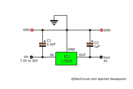
According to the datasheet, the 7905 input voltage is 7.5V to 30V. From my experience, if the input voltage is higher than 15V and the load pulls more than 200mA current, the IC will be hotter than normal because the voltage drop across the input and output is higher than 10V. The power will increase, so we should install a larger heatsink.
If the 7905 is an appreciable distance from a power supply’s filter, we should put the C1 in before the regulator. For better stability, the C1 and C2 capacitors have to be tantalum electrolytic capacitors. If substituted with an aluminum electrolytic type, it should at least have ten times the value.
5V to 25V Negative Variable Regulator Circuit
Apart from that, we can also increase the output voltage by adding in two resistors, as shown below.
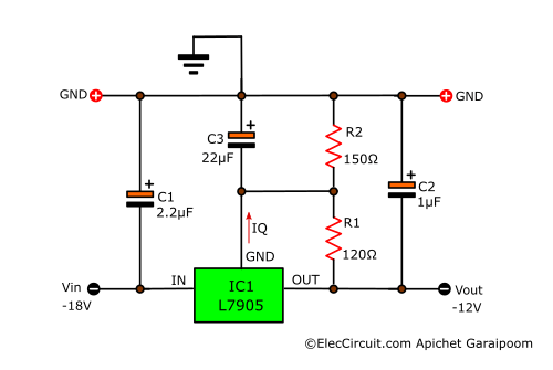
The resistances of R1 and R2 will determine the output voltage, and we can find the right resistance for our desired voltage by using the following formula:
Vout = 5V + {(5V ÷ R1) + IQ} × R2
Note: IQ = 0.0005A(5mA), R1 = 120Ω, R2 = 150Ω
Vout = 5V + {(5V ÷ 120Ω) + 0.005A} × 150Ω
Vout = 12V
If we already know VO and R1 but want to find R2, we can use the following formula:
R2 = (VO – 5V) ÷ {(5V÷R1) + IQ}
R2 = (12V – 5V) ÷ {(5V ÷ 120Ω) + 0.005A}
= 150Ω
If it is difficult to choose the right resistors, we can use a potentiometer instead of R2, and remove R1.
In this circuit below, we will be using 10K VR1 instead of R2. The output voltage is in the range of 5V to 25V, depending on the VR1 adjustment.
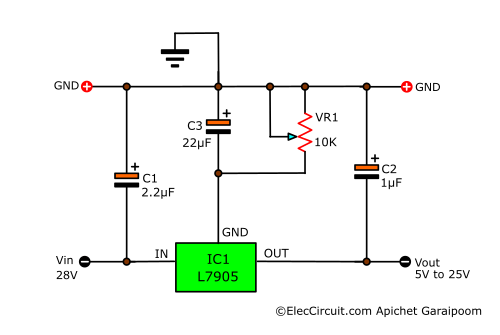
And the C3 reduces the transient noise and ripple voltage.
Dual Adjustable Power Supply Circuit
We often use the 7905 in a dual-adjustable power supply circuit to power an OP-AMP IC circuit.
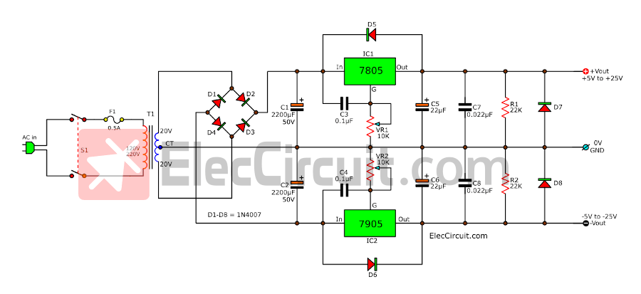
You can read more about this particular circuit here: 7805 and 7905 Dual Adjustable Power Supply Circuit
7905 High Current Negative Regulator Circuit
If we want to increase the current for 7905, simply add a power transistor (2N3055 or TIP3055) to amplify the current from originally 1.5A to 4A, as shown in the example circuit below, which is the 5V 4A negative regulator circuit using 7905 and 2N3055.
The important thing is that the input current has to be greater than 4A, and the voltage has to be at least 10V. Also, nowadays, you should only use a high-grade power transistor.
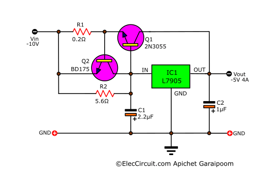
Q2 will only function when the output is short-circuited, as it protects Q1, IC1, and the circuit as a whole. A simplified version of its working process is that when the output is short-circuited, the current flowing through R1 increases exponentially.
This causes the voltage drop across it to exceed 0.6V, causing the Q1 to conduct current between C and E, similar to a closed switch, allowing the VBE between B and E of the Q1 to decrease below 0.6V. This means that the Q1 will stop working and decrease the output current to a safe level.
Component lists
R1: 0.2Ω 5W Resistors
R2: 5.6Ω 5W Resistors
Q1: 2N3055 or equivalent, 100V 15A NPN Transistor
Q2: BD139 or BD175 or equivalent, 80V 1.5A TO-225 NPN Transistor
IC1: L7905 Negative Regulator IC
Conclusion
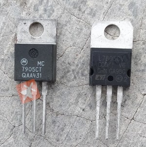
I bought the 7905 IC from a brand called Motorola around 30 years ago, and it functions great and is reliable compared to the regular L7805. In these days, the 7805 has gotten much less expensive; however, its quality and life span have also decreased.
Even though the 7905 IC is designed to be used in a negative regulator circuit, we may be able to adapt or reverse the polarity and use it as a replacement for a standard 7805 IC.
GET UPDATE VIA EMAIL
I always try to make Electronics Learning Easy.
Related Posts

I love electronics. I have been learning about them through creating simple electronic circuits or small projects. And now I am also having my children do the same. Nevertheless, I hope you found the experiences we shared on this site useful and fulfilling.