If you need a high-precision oscillator circuit for a microcontroller, a crystal oscillator circuit is an excellent choice since it has outstanding frequency stability. In this article, we are going to bring up two examples of square wave oscillator circuits; the former has a higher frequency of 10MHz and uses a TTL inverter gate IC, and the latter has a lower 30kHz using a CMOS inverter gate IC.
An oscillator or frequency generator generates various waveforms, such as sine, triangular, and square waves. These are used to control or provide the base time for many electronic circuits.
A feedback oscillator typically uses a transistor or FET as a primary component together with a few other network components. Here are the types of circuit configurations:
- An RC oscillator circuit uses a resistor and a capacitor.
- An LC oscillator circuit uses an inductor and a capacitor.
- A crystal oscillator circuit uses a crystal alongside a resistor.
If you want an oscillator for a microcontroller or digital circuits, you should choose the digital IC as the main component coupled with a crystal and resistor network rather than a traditional RC oscillator, because it has better frequency stability and a simpler circuit design.
High-Frequency Crystal Oscillator Circuit Using 74LS04
First, start with a high-frequency oscillator circuit that generates a square wave or DC pulse. We chose TTL digital IC because it works flawlessly at a high frequency of up to 20MHz.
The circuit below is a simple crystal oscillator circuit using 74LS04 as a main component coupled with a crystal and two resistors instead of an RC network circuit.
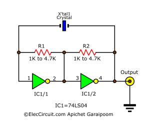
The recommended crystal frequency ranges from 1MHz to 10MHz, and both resistors should be between 1K and 4.7K. This circuit can generate constant frequencies ranging from 1HMz to 10HMz, depending on the crystal.
How It Generates Signal
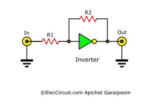
It starts with an amplifier circuit that comprises an inverter gate and two resistors.
To generate an oscillation, we add another inverter gate in series with the old one and two capacitors between them at both ends. We also need to set the resistance of both resistors to 1.2K because the TTL requires a relatively high current to run.
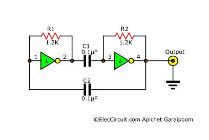
Both capacitors feed an amplified signal from one inverter to the other inverter, creating a positive feedback loop, which causes an oscillation. The oscillating frequency depends on the capacitance of the capacitors that are used to couple the signal; a lower value means a higher frequency.
This type of feedback oscillator is called an RC oscillator because of the use of resistors and capacitors. However, we will remove those capacitors and replace them with a crystal instead; the circuit will still oscillate but at the frequency of the crystal, which is much more stable and precise.
The 74LS04 TTL IC
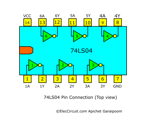
The TTL IC we chose for this circuit is the 74LS04 since it is quite popular and inexpensive. Inside the 74LS04, there are six different independent inverters, a type of logic gate usually used in inverting digital signals. We will learn about them in detail next time, but in this circuit, we only utilize two of the inverter gates.
Apart from the 74LS04, other substitutes are the 74HC04 or the 74HCT04 in case you cannot find one.
5V Regulator Circuit
Next, let’s talk about a power supply. Since the 74LS04 is of a TTL type, it requires a highly stable power source at 5V, but it only has low current consumption. So we will go with this circuit that uses a 78L05 regulator chip.
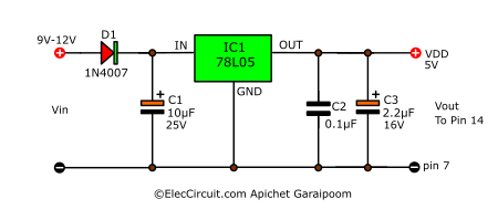
It takes a 9V to 12V input from a battery, an AC adapter, or others, before feeding it to a 5V regulator. To keep the output voltage stable, there are two capacitors, C1 and C3, to smooth up the currents.
C2 will reduce high-frequency noises that are higher than 1MHz. Since it has a very low resistance, the noises will pass through it to the GND.
Assembling and Components List
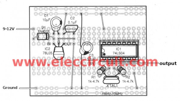
Building this circuit is very simple; we can assemble it on a universal PCB or breadboard using the layout shown below.
The components list
Resistors 0.25W ±5%
R1, R2: 1K to 4.7K
Capacitors
C1: 10µF 16V, Electrolytic
C2: 0.1µF 50V, Polyester
C3: 2.2µF 16V, Electrolytic
Semiconductors
D1: 1N4007, 1A 50V
IC1: SN74LS04, or 74HC04 or 74HCT04 types inverter gate TTL IC
IC2: 78L05, or L7805 5V regulator IC
Others
XTAL1: crystal between 1MHz to 10MHz
Universal PCB board
Testing and Improving the Crystal Oscillator Using TTL 74LS04
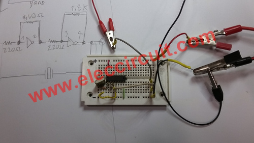
During the testing, we found that adding two more resistors helps with the circuit stability, the resistance of which is shown below.
However, you could adjust the resistance of these resistors freely since they have a minimum impact on the output frequency.
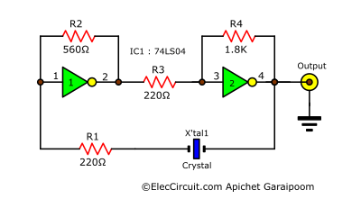
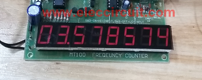
We test this circuit on a breadboard using a 3.579545MHz crystal. Measuring the output frequency reads 3.578574MHz, which is extremely close to the rating of the crystal, with only a 0.027% difference.
Reading of the Output Frequency
Low-frequency Crystal Oscillator Circuit
My friend wants a high-precision oscillator circuit that has a low-frequency output to be used with his digital CMOS binary counter. I think that a crystal oscillator is an excellent tool for the job since I already have a quartz crystal from an old watch on hand.
This crystal has a frequency of 32.768kHz, and we will still be pairing it with an inverter gate IC, but this time it is a CMOS-type IC since it handles well at low frequencies.
The exact chip is the CD4049 hex inverting buffer/converter IC because it is very cheap and can be found easily at electronics stores. This circuit only uses one inverter gate, which is simpler and has higher stability than the TTL previously.
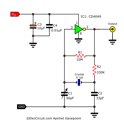
C3 and C4 help reduce unwanted noise that might impact the circuit performance. Another good point of using a CMOS instead of a TTL is that we can power it with a wider range of voltage, from 3V to 16V, but for the most part, we use a 5V power supply because it is cross-compatible with the TTL circuit.
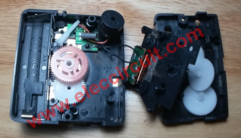
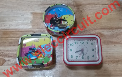
The inside of a cheap alarm clock that we salvaged the crystal from.
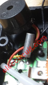
Here is the watch crystal at 32.768KHz
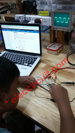
Then we assemble the circuit on a breadboard and take a reading of the output waveform with an oscilloscope; it shows a square wave signal.
He examined test waveform with oscilloscope. It is a square wave signal.
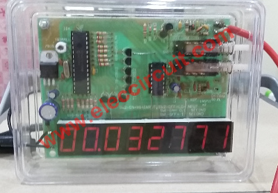
We also measure the frequency with a frequency counter; it reads 32,771Hz or 32.771KHz, which is quite close to the crystal frequency. But we still can adjust it with the C1 trimmer.
The Components List
Resistors 0.25W +5%
R1: 10M
R2: 330K
Capacitors
C3: 10µF 16V, Electrolytic
C4: 0.01µF 50V, Polyester
C2: 33pF 50V, Ceramic
C1: 56pF, Trimmer
Semiconductor
IC1: CD4049 or CD4069 or other Inverter gate CMOS IC
XTAL1: Crystal between 30kHZ to 1MHz
Note: IC can be replaced with a CD4069, but be most cautious since it has a different pinout.
Read also: Clock generator circuit, 60Hz oscillator using MM5369
Conclusion
Those circuits we have tested today have a very high output frequency stability. However, they do have a downside to them, that being the frequency of crystal changes depending on the ambient temperature. Nonetheless, the imprecision is very minor compared to the other feedback oscillators that use an RC or LC network circuit, resulting in a crystal oscillator’s high popularity in a digital circuit.
Or, You can see an Oscillator astable multi-vibrator with the Crystal controller. Below
Check out these related articles, too:
GET UPDATE VIA EMAIL
I always try to make Electronics Learning Easy.

Dear
Readers
I want an CMOS level design of the Crystal wt can i do For that please give any suggestion…
Sir,
I was trying to find the solution for non working of similar circuit made with SN7400, as used in one of reputed working instrument. Your circuit is similar to existing problematic circuit except IC SN7404. Both are not oscillating to any frequency, tried with all version of TTL logic. Can you pl explain the reason and solution for it.Will be obliged for solution through email.
S.K.Sharma.
Hi S.K.Sharma,
Thanks for your feedback.
Please look at: https://www.eleccircuit.com/simple-crystal-oscillator-circuit/
or : https://www.eleccircuit.com/tag/crystal-oscillator-circuit/
if i want to generate 1 Mhz square wave. what are the crystal oscillator, value of R1 and R2 that i should use. Is this design will give out square wave directly?
please can you guys provide voltage divider formula and formula for frequency in the output.
please, what is the working of circuit in detail is not given … that can easy to understand concept and what is use of each component…