These are the wideband active antenna circuits for the SW/MW/FM radio receiver. We can try to test it with many brands of radios.
Why should we use this circuit?
In normal, we short-wave radio receiver. We need to use a long antenna.
But with the helping of this circuit, we can use the only 18-inch antenna. We can receive signals from many band stations around the world more clearly.
I am going to show you 2 circuits ideas. There are differences, in the simplicity and the details of the circuit. Of course, a simple circuit, the quality will suffice for normal use.
But the second circuit has more equipment. So, it has higher efficiency.
Which type will you choose? Start with a simple circuit first, right?
Simple Active Antenna amplifier circuit
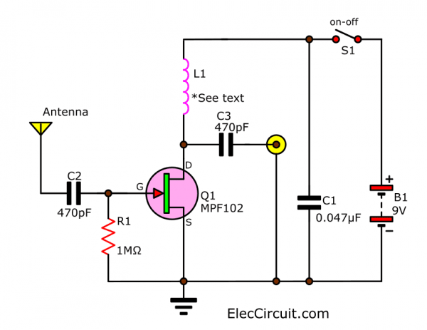
This circuit is the easiest with only one FET. And other equipment just a little more.
In experiments using this circuit with many a short wave radio. They have similar results with the shortwave radio antenna size 20-30 feet.
When used with a conventional MW radio receiver. Previously, some stations were poorly received. It becomes a clearer signal.
And, when using the FM tuner will make for a better signal than the antenna the attached receiver.
What is more? Keeping Read…
How it works
See in the circuit. Is it easy? Yes, it is an untuned circuit. And, the output high impedance is able to work well with a cheap radio.
Which designer wants to use with an untuned antenna like in the car radio.
But we use the active antenna with radio amateur receivers. That has low impedance input. It will not work well.
Also: FET Signal amplifier high impedance (simple circuit)
Experiments built
This circuit is small. But there are details that must be considered as follows.
- L1:
Important to select the L1. That is the RFC – Radio Frequency Choke (RFC) to the appropriate band to use.
In-circuit we coil L1 is 470uH. Because want to amplify the so signal at lower frequencies.
For those who want to apply to the short-wave band. We may use the L1 value as 20 uH.
- This circuit can be packed into a plastic box. If a metal box would be better to reduce noise that may occur better. To make a circuit can work well in the circuit wiring. And connect the antenna cable into the jack and the output should be as short as possible.
- Use the shorter coaxial cable of 50 ohms or 75 ohms from the antenna to this circuit and the radio receivers, too. It will not lose too many signals. The cable is used should be the low capacity like use in the car and should not be used without a shield cover.
- Use DC power supply between 6VDC to 15VDC. In-circuit use a 9V battery.
When some problems occur
In the case of some problems such as:
- There is a strident sound. When listening to some stations. It may cause oscillated with the active antenna and radio receivers. maybe possible that it oscillates with the active antenna and radio receivers. The solution is to reduce the value of L1.
- The power of the 9V battery runs out fast than normal. We should check or change Q1 new.
- Quiescent current is normally of Q1 (MPF102) about 5mA. But maybe increased to up to 20mA. Which needs more power of the battery.
- On using an external power supply circuit. Put capacitor 0.047uF across the rail of power supply to filter any noise. And should be placed close to the Q1.
Parts you will need
- Q1: MPF102, JFET VHF amplifier, N-Channel Transistor
- L1: RFC 470uH or 20 uH see text
- R1: 1M, 0.25W resistor, tolerance: 5%
- C2,C3: 470pF 50V Ceramic capacitor
- C1: 0.047uF 50V Ceramic capacitor
- B1: 9V battery Or Use this 9V power supply
- Others
If the efficiency of the first circuit Not enough for you. Let’s look at the second circuit.
Wideband high-frequency amplifier
This is Wide band high-frequency amplifier circuit, a Wide frequency band between 75-150 MHz, Using transistors, a PNP amplifier. To enhance the signal strength. Before the receiver of the phone. Or FM radio or amateur radio.
If high-frequency signals, in particular, its VHF. The booster circuit is one, serves to amplify the signal strength only.
Operation of the circuit
High-frequency range VHF, inductive antenna, to the emitter pin of the transistor Q1. so circuit held, in conjunction with the bass, a nice low output impedance. You can use a special access code 50 ohms, the antenna on the circuit at all.
The Signal at the Q1 will be expanded to increase. And sent to a tuner or receiver to the receiver.
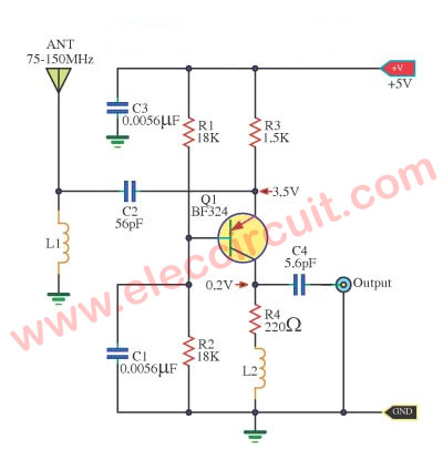
Figure 1 The wideband high frequency amplifier circuit.
The L1 coil wire enamel No. 24 SWG, thousands of rounds of 10, inside diameter 3 mm. And the coil L2 wire number. Thousands of 13 turns, diameter 5 mm. Stent both as a non-core, or an air core.
The power supply is +5 V, this circuit while current is 2.5 mA. If the components to use. Should be based on the antenna. And design of high frequency printed circuit boards as well.
How to assemble circuits
The assembling circuit onto the universal PCB board as Figure 2 May have problems, the interference inserted come in, If assembly circuit to actually use. Should have a basic antenna and PCB design in high frequency reasonable.
The components list
Resistors size ¼ W +5%
R1, R2: 18K
R3: 1.5K
R4: 220 ohm
Capacitors
C1, C3: 0.0056uF 50V
C2: 56pF 50V
C4: 5.6pF 50V
Semiconductor
Q1: BF324___PNP Transistors
Others
L1: is 10 turns of 24 SWG enamel coated magnet wire wound with an inside diameter of about 3mm. no core.
L2: is 13 turns of 24 SWG enamel coated magnet wire wound with an inside diameter of about 5 mm. no core.
The Universal PCB board
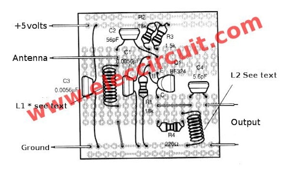
Figure 2 the component layouts of this circuit
High Gain Wideband Active Antenna amplifier
In addition, this signal amplifier from this antenna, also useful as impedance matching.
Between the antenna (high impedance to the operating frequency Because the length is too large) to match the input impedance of the radio receiver. Which is mainly designed for 50 ohms impedance antenna.
Learn: High impedance preamplifier
How it works
This active antenna circuit can be designed to be used with any frequency band. But normally we use with low band frequency – VLF (100kHz or more) Up to 30 MHz.
Because of the antennas of these frequencies are very long. Until most people are unable to find enough space to install the antenna.
See the diagram below, high gain active antenna circuit. This circuit has a gain of around 14-20 dB, covering short-band frequencies to certain amateur frequency bands in the range of 1-30 MHz.
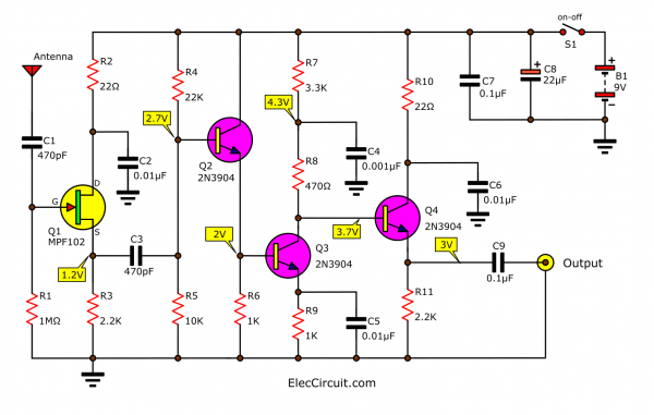
Low frequencies will have a higher gain than a high-frequency band, such as 1-18 MHz will have a high gain of about 20 dB and the gain will be reduced to around 14dB when using a 30MHz frequency.
Circuit concept
In general, the length of the antennas used with shortwave radios is usually 1/4 of the wavelength. Therefore the antenna has a very high reactive impedance. We should use the input of this circuit as a FET better than the normal transistors.
We set it as the source follower circuit. It results in a circuit with a very high input impedance. It is a bridge that makes it very compatible. In connection with the short antenna characteristics That needs to be used with a wide frequency range in the VLF.
We can use many numbers of Q1 as MPF102, 2N3819, or 2N4416. These FETs can amplify high-frequency signals well.
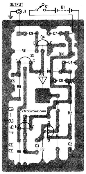
Transistor Q2 is arranged as an emitter follower. In order to use Q2 as a load with high impedance to Q1. While it drives with low impedance to Q3. Which this Q3 is a signal amplifier in the common emitter. For amplifying the voltage gain of the incoming signal.
One of the important parameters of Q3 is the voltage drop across R8. The higher the voltage across the R8, the greater the gain. (Especially at lower frequencies greater than at high frequencies).
Transistor-Q4 is an intermediary for modifying the high-impedance output of Q3 to have a sufficient lower impedance, to drive the signal to the radio receiver. Which has an impedance input 50 ohms. The antenna used with this circuit We can use any type, such as solid wires or Antenna of general radio.
How to build
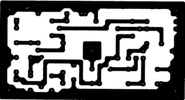
See the copper PCB layout and component layout below.
Choosing and setting circuit
If you want to use it with the frequency range 1-30 MHz. Should find the LC tuning circuit in the middle frequency range instead of R1 in the circuit to prevent other frequency bands Easy to disturb.
But if you want to use with very low frequency (VLF), try increasing the values of C1 and C3. It will make the circuit respond better to lower frequencies.
Same as the first circuit. In this circuit, we can use a wide power supply of 6V to 15V.
The voltage at various points makes the circuit work correctly Which has a discrepancy of 20 percent.
Parts you will need
- Q1: MPF102 or 2N3918 JFET VHF amplifier, N-Channel Transistor
- Q2, Q3, Q4: 2N3904, 0.4A 40V NPN transistors
- B1: 9V battery
- Others
0.25W Resistors, tolerance: 5%
- R1: 1M
- R2, R10: 22 ohms
- R3, R11: 2.2K
- R4: 22K
- R5: 10K
- R6, R9: 1K
- R7: 3.3K
- R8: 470 ohms
Capacitors
- C1,C3: 470pF 50V Ceramic capacitor
- C2, C5, C6: 0.01uF 50V Ceramic capacitor
- C4: 0.001uF 50V Ceramic capacitor
- C7, C9: 0.1uF 50V Ceramic Capacitor
- C8: 22uF 25V Electrolytic capacitor
Here are a few related Circuits you may find helpful, too:
- Signal amplifier circuit diagram with set input-output ratio
- The twin-T complementary amplifier circuit with filter selector
GET UPDATE VIA EMAIL
I always try to make Electronics Learning Easy.
Related Posts

I love electronics. I have been learning about them through creating simple electronic circuits or small projects. And now I am also having my children do the same. Nevertheless, I hope you found the experiences we shared on this site useful and fulfilling.
What couples fail to comprehend is that If they truly want to strengthen their marriage,
they have to think clearly about the reasons
why their marriage isn’t satisfactory.
The bulk of the book describes the correct choice of remedies
that got rid of his tinnitus.
very usefull ckt
When you say MW, I hope you are not talking about microwave fx..Is mw another term for broadband???? Can you give me the exact frequency range using the two different coils ?? This would be greatly appreciated.. Thanks, Rob
MW is medium wave, aka what you have on your normal radio, called AM, so from 530Khz to 1600Khz
Best Project.
Great project !
i can use in this circuit 9v from an external power supply (without battery) and how i change area of capacitor 0.047uF ?
This is the perfect website for anyone who would like to understand this topic.
You understand a whole lot its almost hard to argue with you (not that I really
will need to…HaHa). You certainly put a new spin on a
subject that has been discussed for years.
Excellent stuff, just great!
Man, your English sux. And the coil is once pH, once uH…? So many discrepancies on this page… discourages me to spend time building this.
#Wide band high frequency amplifier
The BF324 transistor has a transition frequency of 450MHz, which is not much higher than common transistors like the 2N3906 (pnp) or 2N3904 (npn). This is one reason why the common-base configuration is used here. A npn transistor like the BF199 might be a better bet, but the polarity of the supply would need to be reversed. As both supply lines are at ground potential as far as signal voltages are concerned, the output could still be referenced to the negative rail.
Thank you very much for your good advice. Your experience is very valuable. Hope to return to visit our website again.
Transistor MP 102 yayılmış sanırım MPF102
Hi hakan
Yes, you are correct. Thanks.
#Wide band high frequency amplifier
Do you have a simple small signal RF Aplifiers that can be used in retrofitting Antique 1920s TRF Radios to operate at lower safer PlateB+ voltages.
Also for building Steampunk TRF Radios Atwater Kent Model 10 Breadboard style
STEAMPUNK Radios two Messages
hi
Do you have Designs/Schematics for simple low-cost RF Amplifiers Hollow State low safe Plate Voltages and Solid State Transistors/Semiconductors?
To be used in retrofitting Antique 1929s TRF Radios as well as building Steampunk Radios Breadboard style, Antique Tuning Components and Modern Electronics ( Variometer, Variocoupler, Variable Condenser/Coil
thanx
73 de jordan ve7jjd [email protected]
————————————————————————-
STEAMPUNK/Retro Modern/Hybrid Radios (Grammarly)
Hi
Looking for comment; advice; assistance; for my Senior Citizens SWL/Scanner/DXing Club’ STEAMPUNK/Retro Modern/Hybrid Radio Receiver/Objet d’art/Plural Objets d’art Project(s)
A) To Retrofit/Restore, Antique/Vintage TRF & Regenerative Receivers to use low, safe, Plate voltages.
B) To Build, Breadboard style, Crystal, TRF, and Regenerative Radios using Antique/Vintage Tuning Components with modern electronics to come up with Objets d’art Sculptures; as well as Functional Radios.
Steampunk combining Antique Components with Modern Electronics. The basic idea is to give the user the “feel ” of 1920s multiple Tuning Controls with modern stable electronics.
The need for assistance is coming up with simple basic RF Amplifier schematics.
Tubes and/or Transistors, especially circuit designs using 12 volt Space Charge Tubes.
Plan A: All solid State
Plan B: All Hollow State
Plan C: Hybrid is Hollow State RF with Solid State Detectors and Audio Amplifiers.
For, Antique/Vintage Radios, the plan is to remove all high voltage Tubes and use the Hardware Chassis Tuning Components and wiring and use RF & Audio Modules/PC Boards; Hollow State, and/or Solid State; mounted on dead tube bases. Minimal disruption to original circuitry so as to be able to reverse changes to allow a conventional restoration. The hybrid comes in with Hollow State for the RF Stages and Solid State Transistor/semiconductor PC board/modules for Detector and Audio; readily available on eBay.
The need for assistance is coming up with simple basic RF Amplifier schematics to build PC Board/Modules Tubes and/or Transistors as well as circuit designs using low plate voltage Tubes.
thanx 73 de jordan ve7jjd [email protected]
Hi, very helpful article, one question though; can I use this circuit with my car radio? I mean the car battery voltage is 12V..
How is the 470 uh coil made?
How many turns, what gauge wire, and diameter of the winding?
Hello, Jack
Thanks for your visit to my site.
It is easy if you buy 470uH coil RFC. https://amzn.to/3JEkM3j
It is a small inductor.
However, In the next opportunity, I will try to build it with resistor and coil. If successful, I will email you to let you know.
Have a good day!