If you need to build the amplifier circuit for your home. The TDA2030 Audio Amplifier Circuit may be the best choice. Why? Because it is a cheap IC and easy to use. Suitable for beginners thought will build the electroacoustic to listen to yourself. These projects use IC of SGS company TDA2030.
TDA2030 Datasheet
Which the SGS said that it is a great power amplifier IC on 5 pins form. And, setting a circuit on a class AB power amplifier.
The TDA2030 has high output current and very low harmonic and crossover distortion.
Also, This device has the short-circuit and the too high-temperature protection system.
As we experiment to build this project and listen to the sound quality nice. We turn the high volume for several hours. The TDA2030 is not hot or just warm. So, suitable for beginners to build this circuit to listen with yourself.
Technical Specifications
- Maximum voltage supply used of +/- 18VDC
- Begin working at the minimum voltage of +/- 6VDC
- Power driver output 14W at 4Ω and 9W at 8Ω
- The maximum current of 900mA
- Frequency response range 10HZ-140KHz at -3dB
TDA2030 Pinout
I like this IC. Because it looks like transistor on TO-220, mini size. So, it is so easy to install on a heatsink.
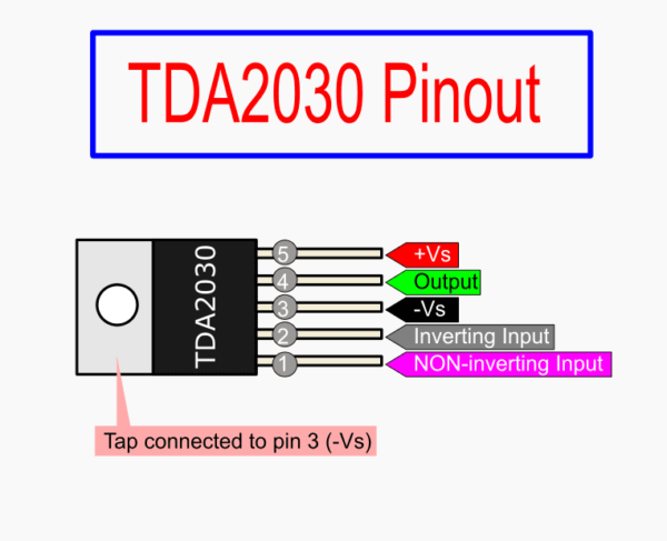
Look at a pin connection of top view. The tap connects to -Vs pin.
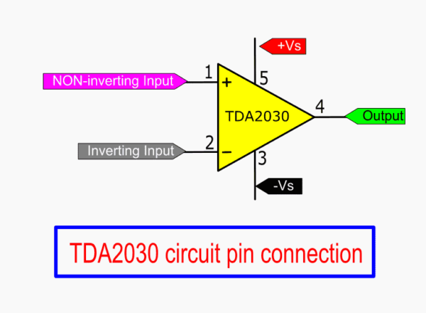
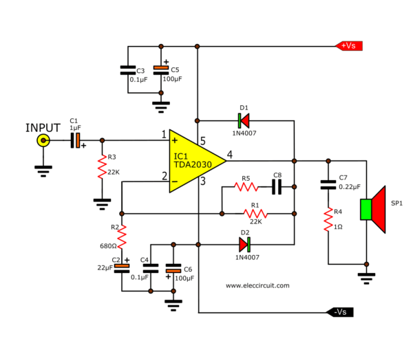
Look at the typical Application circuit diagram.
Also, you look at its circuit symbol pin connection below.
The TDA2030 integrated circuit is the best choice to make a good audio amplifier circuit. It is used to make many amplifier outputs 10 watts to 200 watts.
And a lot of types, Mono or Stereo, OTL, OCL, BCL (Bridge amplifier).
For Example, the super Bridge 120 Watts—I love it. Because of small, easy using, and cheap.
For Example TDA2030 Circuits
Are you interest in it? Let’s see we can apply it to what circuits.
1# Small Versatile Power Amplifier, 12W OTL
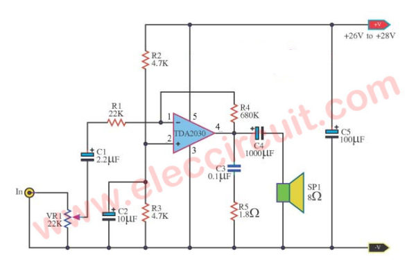
The multi-purpose Amplifier using TDA2030 circuit. It has power 8W(RMS) at 8Ω loudspeakers.
It has low noise be valuable THD (Total harmonic distortion) 0.1%.
When friends use Power supply Voltage Source 28V at 4Ω loudspeakers. It has the output power of 12W.
But be high class the noise increases to are 2 times.
Besides still three be usable with Volt supply about 9V. But there is the electric power is down respectively.
The VR1 use for the Volume popularity level of a sound signal.
If you cannot find a 22K potentiometer. You can use 50K instead.
See next circuit are better.
Recommended: Do you want higher output power than this?
Use TDA2050
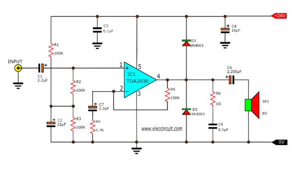
2# Mini 15W OTL Power Amplifier with PCB
This is the main power amplifier of 15W OTL at 8Ω loudspeakers.
You should use a power supply of at least 24V 1A for MONO.
15 watts Audio Power Amplifier
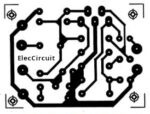
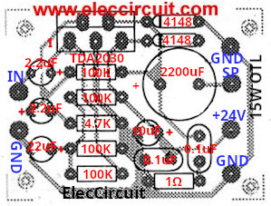
It is specified with the PCB layout you can try to build this project.
PCB of 15W OTL Power Amplifier using TDA2030
Components list
IC1: TDA2030 18W hi-fi amplifier and 35W driver
D1, D2: 1N4001, 50V 1A diodes
Capacitors
C1, C7: 2.2uF 50V Electrolytic
C2: 22uF 25V Electrolytic
C6: 2,200uF 25V Electrolytic
C5: 0.1uF 50V Ceramic
0.25W Resistors tolerance: 5%
R1, R2, R3: 100K
R4: 4.7K
R6: 1Ω
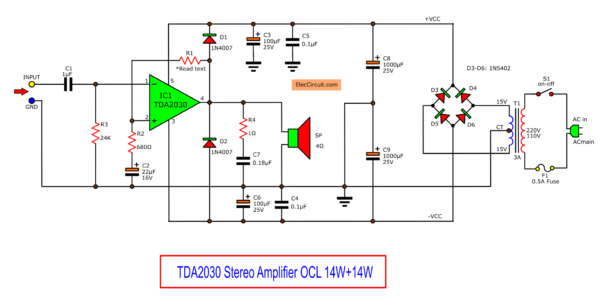
3# 14W TDA2030 Stereo amplifier circuit
This is a TDA2030 stereo amplifier circuit. It is a special project.
Because it is an OCL-type amplifier.
Which provides a power driver of 14 watts/channel at a load of 4 ohms.
So, it is suitable for beginners thought will build electroacoustics to listen to themselves.
This project uses the IC of The SGS company number TDA2030.
Which SGS said that TDA2030 is a power amplifier IC in 5 pins form.
The Setting circuit on a class AB power amplifier to the output of the high harmonic distortion and low crossover.
They are ready, shock output protection, and the temperature is too high, complemented within the integrated circuit.
As we listen to the sound quality nice. We turn the volume fully to several hours. The IC is not hot. Or just warm. so, suitable for beginners to build this circuit to listen with yourself.
Technical Specifications of IC-TDA2030
- Maximum voltage supply used of +/- 18VDC.
- Begin working at a minimal voltage of +/- 6VDC.
- Power driver output 14 watts at 4 ohms and 9 watts at 8 ohms.
- The maximum current of 900mA.
- Frequency response range 10HZ-140KHz at -3dB.
How this circuit works
In the circuit, the figure is a single channel amplifier. You will see that have very few parts. Both pin 1 and pin 2 of IC-TDA2030 input.
The pin 1 is non-inverting input and pin 2 is inverting input. Then input of power amplifier comes to C1 into pin 1 of IC.
- The R3 determines the input impedance of the IC.
- Pin 3 is -VCC leg or negative voltage, and pin 5 is a +Vcc or positive voltage.
- Four capacitors C3, C4, C5, and C6 are bypass filter voltage +Vcc and -Vcc.
- R1 as acts adjust the gain of IC with a negative feedback form. If R1 has higher resistance. Then, the gain rate of IC rises up as well.
- The R4 and C7 are protectors a oscillated high frequency.
How to build
First of all, you need to have all components list below.
Parts you will need
MONO form
IC1: TDA2030 18W hi-fi amplifier and 35W driver
D1, D2: 1N4007, 1000V 1A diodes
D3-D6: 1N5402, 200V 3A diodes
Capacitors
C1: 1uF 50V Electrolytic
C2: 22uF 16V Electrolytic
C3, C6: 100uF 25V Electrolytic
C4, C5: 0.1uF 50V Mylar
C7: 0.18uf 50 Mylar
C8, C9 1000uF 25V Electrolytic
0.25W Resistors tolerance: 5%
R1, R3: 24K
R2: 680Ω
R4: 1Ω
Others
PCB, Heatsink, etc.
Note: You may buy components at electronics stores here.
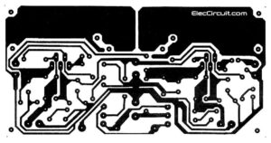
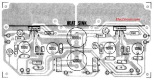
Then make a PCB as figure 2. Next solder all components on PCB as Figure 3.
Copper PCB layout of TDA2030 stereo amplfier
Components layout
You need to put all parts correctly on PCB. Even You need to be careful putting the polarity of the electrolytic capacitors and Diodes right ways.
Recommended:
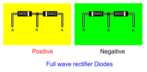
Full wave rectifier diodes
In the component layout, use both full wave rectifier diode that has three lead. For positive has A K A
And negative has K A K lead. It may be an old part. So you can apply two diodes connection as below circuit diagram.
How to install TDA2030
The IC is the final sequence. You should install with a heat sink first. Then, Solder it on PCB. Because of if soldering IC first. The Holes between the ICs and the heat sink may be mismatched.
When all things are complete. Then, connect the speakers to the output. And connect the ACV of transformer current at least of 2A, ACV 12V CT 12V or 15V CT 15V, One or the other to the power connector terminal.
Testing
Our amplifiers are ready to test. We use a finger, touch input on both. It will noise of the hum out of the speakers. That sound is good. Then, use a good quality tone controls. To test the complete sound again.
Download this
All full-size images of this post are in this Ebook: Elec Circuit vol. 2 below. Please support me. 🙂
4# 120 watts Subwoofer Power Amplifier
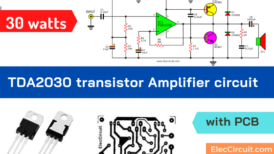
5# 30 watts TDA2030 transistor Amp with PCB
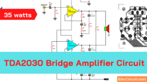
6# TDA2030 Bridge Amplifier circuit, 35 watts
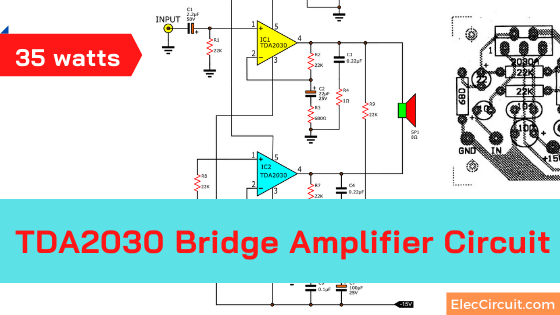
If you want a higher sound than only one. You can use this circuit. We called the TDA2030 Bridge amplifier. It is direct coupling to a speaker to be like OCL amplifier. But uses two ICs and more current in Still using the same voltage. Continue reading
You may like these circuits, too.
More external circuit ideas
TDA2030 Audio Amplifier Circuits
GET UPDATE VIA EMAIL
I always try to make Electronics Learning Easy.
Related Posts

I love electronics. I have been learning about them through creating simple electronic circuits or small projects. And now I am also having my children do the same. Nevertheless, I hope you found the experiences we shared on this site useful and fulfilling.
i have made the circuit bridge120W by i.cTDA2030 as per the circuit and pcb given but it does not work why? i do not know all connections and wiring has been checked could any help me in this matter
i have made the circuit bridge120W by i.cTDA2030 as per the circuit and pcb given but it does not work why? i do not know all connections and wiring has been checked could any one help me in this matter
3# 14W TDA2030 Stereo amplifier circuit
What are “aka” and “kak” coded parts near 1000uf capacitor? Are they rectifier diodes?
Yours Sincerely…
Hello sir, am Jackson, the coded aka and kak means you have to connect diode in the following arrangement
AKA- Anode-Cathode-Anode, and KAK- Cathode-Anode-Cathode.
3# 14W TDA2030 Stereo amplifier circuit
C8 should be at least 1000µF. C8=C9. C3 and C6(100µF) are useless as long as C8 and C9 are ten times greater(they are in parallel).
Pin 2 of two IC TDA2030 mustn’t connect Power.The Power will be connected with pin 5 of two IC TDA2030.Negative (pin 2) pole and positive pole(pin 1) connect with Audio signal…
such as: https://www.eleccircuit.com/the-otl-amplifier-listen-comfortably-by-tda2030-and-tip41tip42/
What is. Correct way?
Anyone know the proper connections.???.
The problem is on the 2030 chip you have pin 3 and 5 reversed . Pin 1 is + and pin 5 should be on the same side in the schematic. Pin 2 is – and pin 3 should be on the same side in the schematic. Easy mistake
pls give me a 5.2 channel circuit
simple ic transistor based
with power supply
Can we use the tda2050 place of tda2030, what watts of that type amp
3# 14W TDA2030 Stereo amplifier circuit
can i use 12 0 12 1A transformer??
no u can not use ….
Hello Akshay,
Thanks for you visit. I like your question.
If you use 12 CT transformer. The output DC voltage will be 17V. It makes output is lower sound than 15V transformer. (21VDC output).
Have a good day.
Thanks
Apichet
how many inch speaker it take load
There is little mistake in the circuit.if the output is 120watts then the power transistor getting DC+ voltage via TDA2030 ? It must be in parallel to 2.2ohms supply. it will not work in 6volt DC. It requires 12V/7Amps free from rippling DC.
TRANSISTOR COLECTOR LEG
yeh… i hav made dis circuit…
the sound quality is nice.
but the bass reflex is very poor..
i replace both TDA2030A IC to TDA2050..
and added one 1mF caps at the (+ve) input signal
and added one 2000mF caps at the output signal..
now the bass and the output power is increased to more… then before it has.
Is this circuit runs well? there is no rectifier in this circuit. so, will this circuit will run connecting 15 volt 2 amp transformer directly to the circuit board?
Hi everybody,
The circuit has many problems and it should be rectified before building this.
So if you are searching for tda2030a or tda2050 Integrated Circuits then you may visit the links below
Here is the complete Youtube video for building a stereo amplifier based on tda2030a great IC
and here is the complete PCB board and notes for building this great project
For more information contact us.
Me I have problems with the loadline protection for amplifier in circuit
Hey…i want to knw exacly can this curcuit use 2OHM speaker load?coz on explanation above blabla watt reach 200w on 2ohm load..so that mean admin already test it on 2ohm without anyfailure overheating etc??The connection between PIN R4 and R8 2.2k resistor..the line conected like that way?i feel something not right on this schematic,,,U sure r4 & r8 connected that way??
pls dont confuse us on this all things right here..coz if something doesnt right happen our $$$ fly away…maybe cheap on u country but on my country???this chip reach $15.00 each for tda2030 /TDA2030A.power transistor O_O $ 14.00 each so 2 pair = 14×4,,the capasitor for ps also walla..50v/10000uF reach $46.00 each..
I rebuilt the circuit. One of the output tranisistors was blown up. There was also a bit of “Magic smoke”.
I hoped better caracteristics from this circuit.
I want to purchase plain pcb of 120w audio circuit. About 50nos
Please call me to get PCBs. 9826088782 and [email protected]
Can i use 15 volt 4 amp transformer for this circuit?
Hi Justin
Yes you can use it.
I wanted to visit and allow you to know how considerably I loved discovering your
blog today. I will consider it the honor to operate at my workplace and be able to make real use of the tips provided on your web-site and also engage in visitors’
responses like this. Should a position involving guest publisher become on offer at your end, make sure you let
me know.
Hi guys..I am beginner and need to know do any can replace burned IRF540 mosfet.my mean I want repair it but wanna using another part with sama or close spec of part
TDA2050 alternate IC result original quality mic match IC?
Hello Jagadeesh. M
Thanks for your visit. Yes, You can use TDA2050. It has more power than TD2030. In the same size
Thanks
Apichet
Thanank you very much to share your experiance. Your circuits and books are so usefull for me. And now i am waiting for book vol:3…
Thanks again and May u live Long!
From: Umar Saafi Owner at Al-Buraq Electronics Pakistan.
Hello Umar Saafi,
Thanks a lot for your text. It makes me powerful.
For book vol 3. I am not sure when it be finished.
Have a great day to you and your family, too.
I want to know what should be the correct size (length and width) of heatsink for this Ic if I want 10 watts output @4 ohms on 12-0-12 V transformer ? I searched a lot online but nowhere Heatsink details are given & on datasheet it’s confusing for me so please tell me.
Greate post. Keep posting such kind of info on your site. Im really impressed by your blog.
Hi there, You have performed an incredible job. I’ll certainly digg it and personally suggest to my friends. I’m sure they’ll be benefited from this site.
It’s my pleasure. Your message was a great encouragement to me and Dad, I’m so glad you thought it was good for you. I will study electronics to get better no matter how slow my brain is. But I will learn. Even though it is difficult for me, I think in the future we may use our knowledge about electronics. I hope you will continue to follow us. 🙂
As you can see they only give you sound connection but how did you connect your mp3 players, transistor for powering MP3, the 12v or 18v to power the circuit board and many others