This is TDA2822 small stereo power amplifier. People like TDA2822. Me too. Why?
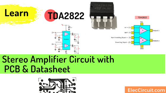
- Dual Amplifiers in one DIP-8 similar for LM368.
- Give power watts at 1W + 1W at 4 ohms speakers.
- It is enough. We are happy Listening in our corner.
Relax… - Start voltage supply of 1.8V to 15V. The wide a lot.
- Save energy with only 6mA, Min.
- The bandwidth expansion rates at 40dB 120kHz.
- Cheap and easy to use
Note:
You can read more datasheet below.
It is a great idea.
You test the Arduino as a midi player. But its output is too weak.
You should increase the sound louder.
The TDA2822 is a 5V audio amplifier to this. It is one of a low voltage amplifier that is easies in the stereo system too.
Did you try it? You may like it same me. I will show you the TDA2822 Stereo amplifier project with PCB.
TDA2822 Stereo amplifier circuit working
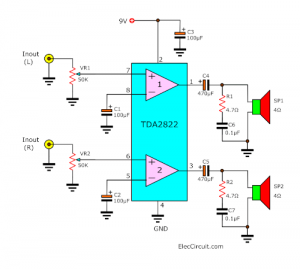
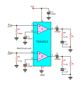
Look at the circuit diagram. It is a stereo system. Both channels are the same.
To begin with, the 9V from power supply—battery goes to the circuit. And, C3 is a filter capacitor to keep this voltage is more stable. When sound is too fluctuating.
Then, the stable voltage flows pin 2(Vcc) of IC1. And, negative voltage connects to GND of the circuit.
Both input signals left and the right pass VR1 and VR2. To adjust the volume of the music.
And, these capacitors C1 and C2 keep circuit stability and block DC voltage.
Next, the signal flows to inputs pin7,8 and pin 6,5 in sequent.
The circuit inside IC runs, It amplifies more power of sound.
The stronger signals come out of pin 1 (left output) and pin 3 (right output).
Also, C8 and C9 are the output capacitors to coupling the strong signals to the speakers.
And both The C6, R1 and C7, R2 reduce noise to the output.
How to build this project
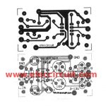
This project is a simple stereo amplifier in small size PCB see in Figure 2 and you can put all parts in the components layout.
Figure 2 the PCB layout and the components layout of a stereo small amplifier using TDA2822
Stop! This is low watts for you, right?
Look:
The components list
IC1: TDA2822_DUAL POWER AMPLIFIER
Electrolytic capacitors
C1, C2: 100μF 16V
C3: 100μF 16V
C4, C5: 470μF 16V
Polyester capacitors
C6, C7: 0.1μF 50V
VR1, VR2: 50K_Potentiometer
B1: 3V to a 9V battery Or 9V power supply circuit
Speaker 4Ω
Note:
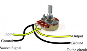
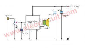
My friend asks me how to connects the potentiometer to this project.
Please look at Figure 3
TDA2822 datasheet-Dual power amplifiers
This is TDA2822 datasheet as a dual power amplifier in portable radio on DIP 8pin. We can use as stereo configuration and Mono (Bridge audio amplifier).
Features
Short features as follows:
- The supply voltage down to 3V can use with AA 3V battery.
- Wide supply range 3V-16V
- Up to 2W + 2W output power(highly popular).
- Low crossover distortion
- Low quiescent current.
Keep Reading
- 4 Preamplifier circuits using Transistors
- Video amplifier splitter using transistor
- The Op-amp IC tester circuit
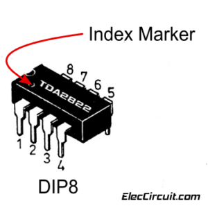
TDA2822 Pinout
Even its shape is as same as the famous 741 op-amps circuit. But TDA2822 pinout is different. Please be careful. See!
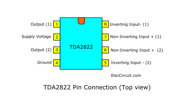
Pin connection (top view)
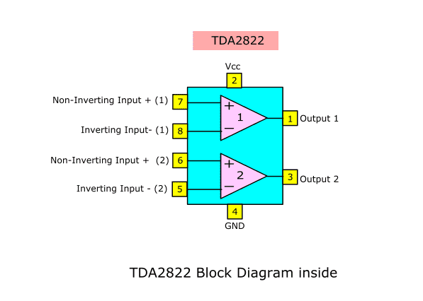
And, inside TDA2822 has 2 Op-amps is similar for 741. But It has a lot of components more than.
With the power amplifier section.
Testing circuit
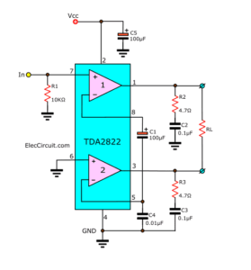
We can test this IC with 2 basic circuits.
Look:
Stereo module and Bridge module.
The stereo—output 1W + 1W of typical application circuit
The Bridge—output 4 watts max of the typical application circuit.
Although Both are a testing circuit. But you can really use. Because It can get a great output sound on 4-8 ohms speaker.
Download This Post as a PDF and all PCB layouts
External Idea circuits
TDA2822 Stereo Audio Amplifier Circuit
TDA2822 Dual Low-Voltage Power Amplifier, DIP-8
You may also like these circuits
- BA5406 amplifier Stereo 3W
- Small Home Bridge amplifier with tone control
- LM386 audio amplifier circuit with PCB
That’s not all…
Look:
Audio amplifier circuit diagram with layout

I love electronics. I have been learning about them through creating simple electronic circuits or small projects. And now I am also having my children do the same. Nevertheless, I hope you found the experiences we shared on this site useful and fulfilling.
Dear Sir,
We are interested in assembling car stereo cabinet with usb/mmc, Please send us the circuit diagram, with product cataloger and the cost and also send us your different range of products.
With Regards,
Solomon
91-9505303636
Hi, Han.
Thanks for your comment.
gracias por el aporte me puedes decir cuales son las medidas del pcb por fa
thanks for the contribution What can you tell me the dimensions pcb son by fa
it can give brass bosst
Thanks.
your scentences are too long and don’t make any sense.
you need to improve your grammar.
this circuit is so nice and i’m thankin’ for designers,thx alot.
Hi, someone
Thanks for your feedback.
Yes, my English is poor.
If your projects finished please share me.
Hi, hirwa juldas
Thanks for your feedback.
please sir some doubt in your project : in circuit R1 4.7 but in your parts list is not included this item, what item this pleas explain me please and what is input output?
Hi,Sir How to produce negitive voltage(-12v)
with out using ic
if in case we can use ic wich no of ic can be use
thanks may God increase your knowledge
very gooooooooooooooooooooooooooood
Hi seyed,
Thanks for your feedback.
Dear sir,
How to insert the microphone in this circuit
where is the ground source signal and ground circuit?
please can someone tell me what the sound quality is like
I made it and its works well but i change the C Out filter value to 33nF and its still works well!
btw thanks for PCB Layout
Where is the potensio??
El circuito no se corresponde con los componentes, pones 2 condensadores de 0,1 y en el pcb solamente hay sitio para uno, pones condensadores 470 25V y en el circuito son de 16V, si vas a subir algo , nadie te obliga pero si lo haces,hazlo bien, porque hay gente que cree que puedo montarlo y luego se encuentra que falta información o está mal puesta.
The circuit does not correspond to the components , put 2 capacitors 0.1 and the pcb there is only room for one , put capacitors 470 25V and 16V circuit are , if you go to upload something , nobody forces you but if you you do , do it well , because people think I can mount it and then that information is missing or misplaced .
it is good.
Work whit small sound quality
please help me ,i want to design a 50 watts power audio amplifier using TDA2025 IC,I NEED THE CIRCUIT
Hola,tengo un minicomponente philco ph 400,se quemo el fusible de la fuente conmutada y uno de los transistores conmutadores,haciendo un puente tengo tension en todas partes menos en el ci de audio de potencia tda7265,podrias de cirme que metodo usar en la reparacion.Gracias,un abrazo.
Hello, Jose faiad
Thank you for visiting. Your language is Spanish, right? I use google translate. Do you want to repair mini component Philips 400? I don’t dare to give advice. It may slow you down. Waiting for other people to recommend.