Here are a few sound-effect generator circuits using the UN3561 IC and a handful of other components. It is capable of generating four different sounds, which are an ambulance siren, a police siren, a fire engine siren, or even a space machine gun sound, all from a relatively small, simple, and inexpensive circuit.

Typically, if we wanted a siren sound generator circuit, we would use the NE555. However, it is quite complicated to use, and its performance is modest; thus, we will use the UM3561 instead.
Characteristic of UM3561
The UM3561 is an integrated circuit that includes an oscillator and a selector circuit. It also contains a preprogrammed memory used to reproduce sound effects. Mainly used in a toy or small electronics application, the UM3561 CMOS LSI can be used to create an inexpensive, compact, low-power sound generator with the addition of only a few other components.
Features
- Three alarm sounds and one sound effect
- Typical operational voltage of 3V—min. 2.4V and max. 3.6V, normally sufficient with two 1.5V AA batteries.
- Typical operational current of 150μA
- Capable of driving a magnetic speaker with the help of an NPN transistor
- Maximum output current of around 3mA
Pinout

It uses the same DIP-8 package as a NE555, meaning that it is fairly easy to use. The descriptions of each individual pin are as follows:
- SEL2 is the sound effect selector pin.
- VSS is a negative power supply (GND).
- OUTPUT is monotone output.
- NC is used for testing—leave open in normal operation.
- VDD is a positive power supply.
- SEL1 is the sound effect selector pin.
- OSC1 is an RC oscillator pin.
- OSC2 is an RC oscillator pin or inverted clock output.
Oscillator Circuit
There are two options to set the oscillator frequency: first, one external resistor between pin 7 (OSC1) and pin 8 (OSC2); second, an integrated oscillator resistor.
Sound Effect Selector
Pin 6 (SEL1) and pin 1 (SEL2) are used in combination in order to select the sound effect. SEL1 also has three state inputs.
Sound Effect ROM
These are the sound effects that are preprogrammed into the chip and are selectable with the two selector pins. To select an individual sound, apply a combination of input to SEL1 and SEL2 as shown in the table below.
| SEL1 (Pin 6) | SEL2 (pin 1) | Sound effect |
| Disconnected | Disconnected | Police siren |
| VDD | Disconnected | Fire engine siren |
| VSS | Disconnected | Ambulance siren |
| Overwritten | VDD | Machine gun sound |
Sound Generator Circuits Using UM3561
Let’s take a look at some of the example circuits.
Simple 2 Siren Sounds
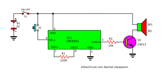
We will start with a circuit that generates two siren sounds, which are (1) police siren and (2) fire engine siren. When we turn on S1, the circuit starts functioning, while we can select between the two sirens using S2. For instance, if we turn off S2, it will play a police siren because both pin 6 (SEL1) and pin 1 (SEL2) have no connection. But when we turn on S2, pin 6 (SEL1) connects to VDD, meaning that the fire engine siren plays instead.
This circuit is notable for its simplicity, with only a few components: R1 to determine the frequency and Q1 to amplify the output to the speaker.
Simple 3 Siren Sounds
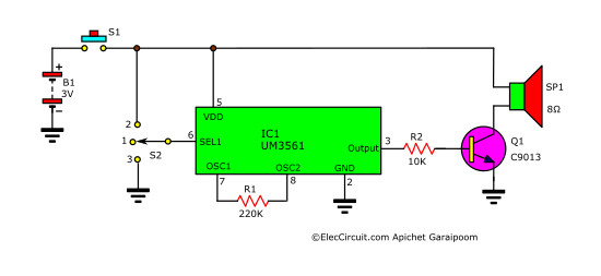
Next is a circuit that can generate one more siren than the previous circuit, bringing the total to three: (1) police siren, (2) fire engine siren, and (3) ambulance siren. One difference from the previous circuit is that the S2 is now a three-position on-off-on toggle switch.
When we turn S2 to position 1, or off, the police siren will be played because pin 1 and pin 6 are disconnected. But if we turn S2 to position 2, it connects pin 6 to VDD and thus plays the fire engine siren. Lastly, if we turn S2 to position 3, pin 6 will be connected to the VSS, causing the IC to play an ambulance siren.
Improved 4 Sound Effects
The UM3561 can also be set to generate a machine gun sound as well, making the total number of generateable sounds 4, including the 3 sirens. This circuit uses three switches to select between the four sounds.
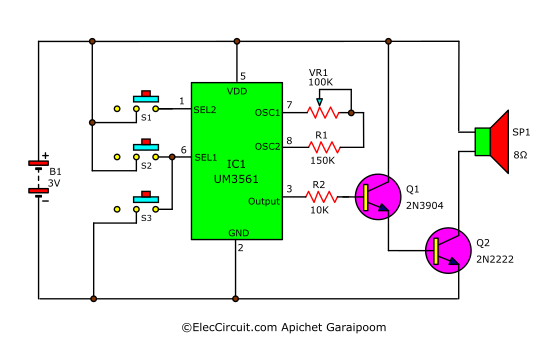
The combination of switches for each sound is as follows:
- Police siren—set all switches to off.
- Fire engine siren—leave S1 and S3 off, turn on S2.
- Ambulance siren—leave S1 and S2 off, turn on S3.
- Machine gun sound—leave S2 and S3 off, turn on S1.
Since the two previous circuits are not very loud, we add another transistor in the form of a Darlington pair to increase gain for the speaker.
And add a VR1 potentiometer in series with R1 between pin 7 and pin 8 to control the frequency of the oscillator circuit inside the IC.
Parts List
IC1: UM3561
S1-S3: normal SPST slider switches
Q2: 2N2222, or equivalent, 0.8A 30V, NPN transistors
Q1: 2N3904, or equivalent, 0.3A 20V, NPN transistors
SP1: 8Ω 0.25W speaker
VR1: 100K potentiometer
R1: 150K 0.25W resistors
R2: 10K 0.25W resistors
Practical 4 Sound Effects Generator Circuit
Finally, let’s look at a circuit suitable for general use; it is louder and more practical than the previous circuits. Part of that change is the sound selector; using a combination of switches is tedious, so we are replacing it with a 4-position selector rotary switch instead.
How it does works
Similar to the previous circuit, R1 is connected to pin 7 and pin 8 of IC1, which are OSC1 and OSC2, respectively; it controls the frequency of the oscillator inside IC1. The lower the value of R1, the higher the frequency; conversely, the higher the value, the lower the frequency.
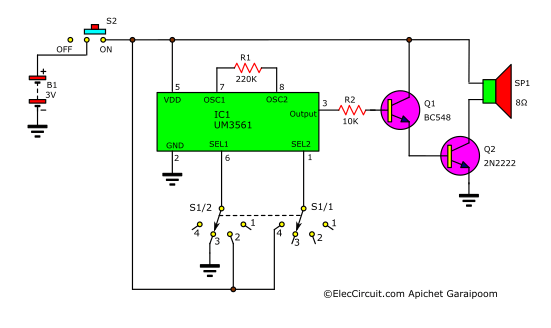
The positions of S1 for each sound are as follows:
1. Police car siren—pin 6 (SEL1) and pin 1 (SEL2) are left disconnected.
2. Fire engine siren—pin 6 (SEL1) connected to VDD, pin 1 (SEL2) disconnected.
3. Ambulance siren—pin 6 (SEL1) connected to VSS, pin 1 (SEL2) disconnected.
4. Space machine gun sound—pin 1 (SEL2) connected to VDD, pin 6 (SEL1) disconnected.
After the selectors SEL1 and SEL2 select a sound to be played, IC1 will then choose from the preprogrammed signal in its memory that corresponds with the option selected before sending that signal to the audio generator circuit to generate sound.
The preprogrammed signal is output through pin 3 of IC1, then it goes through R1 before being amplified by transistors Q1 and Q2. The R2 serves to limit the bias current for both transistors, which will drive the speaker. However, if you need the sound to be louder still, you can connect the output signal from pin 3 to a high-gain amplifier as well.
How to build
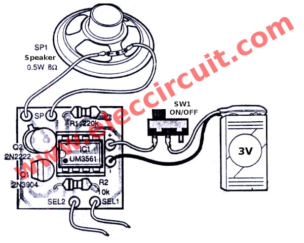
Because this circuit only has a few components, it can be assembled on a universal perforated PCB. But we are going to build ours on a dedicated PCB as shown in the picture below.
If you want to use the design and build it for yourself, please let us know, and we will publish the PCB for you to try out.

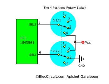
I use 12 Pins, 3 Pole, 4 Position Selectable Single Deck Band Selector Rotary Switch, for select the sound output by connecting wires.
I use this 12-pin, 3-pole, 4-position, selectable signal deck band selector rotary switch for the sound selector. You can check it out here.

Testing
After applying the power from two 1.5V batteries, there should immediately be sound played from the speaker. Next, try turning the selector switch to see if the sound changes as anticipated. As for its application, you use it in a toy for kids as it is designed for, or even integrate it into a theft alarm or home security system.
Parts List
Resistors 0.25W 5%
R1: 220K
R2: 10K
Semiconductors
Q1: 2N3904 or equivalent
Q2: 2N2222 or equivalent
IC1: UM3561
Others
S1: Slide switch 3 lead
S2: Selector switch 4 steps
SP1: 8Ω 0.5W Speaker
3V (2×1.5V) AA batteries and snap connector
Conclusion
As you can see, the UM3561 chip can be used to generate siren sound output without much work. One prominent point that I like about this IC is that it only requires two 1.5V batteries to operate; it only consumes 150μA of current. Furthermore, adapting it to use with another power source is also relatively easy, only needing to drop the voltage down to 3V. And of course, we can add an amplifier circuit as needed.
GET UPDATE VIA EMAIL
I always try to make Electronics Learning Easy.

I love electronics. I have been learning about them through creating simple electronic circuits or small projects. And now I am also having my children do the same. Nevertheless, I hope you found the experiences we shared on this site useful and fulfilling.


Donde comprar el circuito UM3561 para un rápido envío
Agradezco su atención
i want to buy this circuit ant its componants. How ?
I want the write up for a 555 siren sound generator i dnt mind buying it
Good Circuit!!!
Hi MR OHM 1970
How are you today?
Thanks for your feedback.