This small RF remote control or Radio Control (RC) circuit is easliy. It can install with a toy train or automobile that used a voltage supply from 6-12 volts. Which the radio receivers sectors is installed in the car will turn on – off the DC motor runs by forcing the rhythm on – off of the transmitter radioInstead of using a switch turns on-off in the car.
The principle of circuit on the radio receiver section.
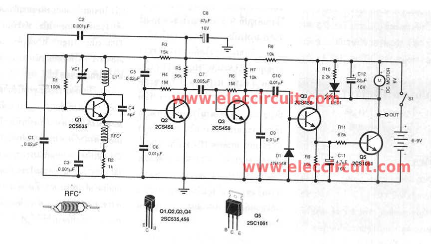
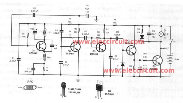
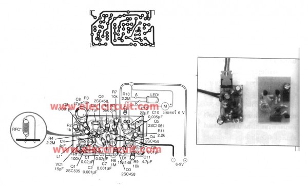
The circuit in Figure 1. is simply a receiver and controller. By the high frequency receiver that is in a Q1(2SC828 or 2SC458) act received the radio frequencies. In rang 270-300 MHz. There is a trimmer -VC1 is determiner a value of frequency receiver in conjunction with, L1 Is high-frequency coil.
Figure 1.
So if adjusted Trimmer will make receive frequency changes according to the value as above. Radio frequencies that incoming is converted into a low power audio signal. So need to use Q2, Q3(2SC828 or 2SC458) acts amplifiers from The circuit in part of Q1. To lead the sound, From the transmission sector incoming through power amplifiers. Which is to receive audio through the expansion From Q2, Q3 through C10. To the base of Q4(2SC1061 or TIP41) To conduct current through R11 to control the Q5. Which is transistor drive the DC motor rotate and LED1 flashes with the beat. Delivery – receive signals from the transmitter. They will be able to control or stop the car as needed.
Recommended: How does a SCR thyristor work?
The principle of circuit on the radio transmitter section.
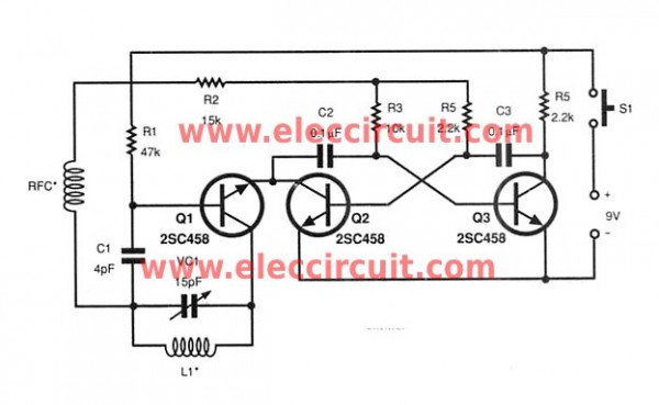
The circuit in Figure 2 is the transmitter circuit with a simple principle. Operation just like The radio transmitters or a normal wireless microphone circuits. By Q1(2SC828 or 2SC458) acts as high frequency radio generator. It can Change the the transmited frequency output by changing adjusted VC or a trimmer in there.
Figure 2
Specific radio transmission to the receiver can not work. So must have a tone generator circuits. With Q2, Q3 In conjunction with C2, C3, R3, R4 and R5. Created tone frequency is mixed with the radio broadcast of Q1 and then sent to the receiver. To control motor and LED contacts.
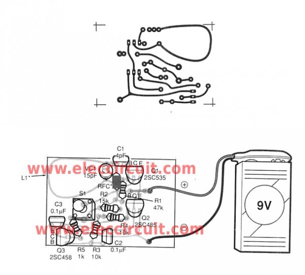
Figure 3 is the PCB layout of the transmitter circuit
Figure 4 is the PCB of the receiver circuit
This circuit requires enough power supply. Do you have this one? If you do not have it. Look:Learn Many Power supply circuits
How to builds
On Figure 3 is the PCB layout of the transmitter circuit. And Figure 4 is the PCB of the receiver circuit. Details about soldering equipment. I do not say again Because There are several articles already, Friends certainly would not like to read.
Note: In the receiver has L1 is high frequency coil. Using a wire enameled copper No. 22 SWG, length 4 cm. Shaped curve Is U.
RFC, is high frequency coil Shock. Enameled copper using a wire No. 40 SWG. Revolves around the 0.25 watt resistor 2.2M for 30 rounds.
and on the transmitter section : The trimmer capacitors of 15pF.
– L1 is high frequency coil (on the PCB).
– RFC is is high frequency shock same as the receiver sector.
GET UPDATE VIA EMAIL
I always try to make Electronics Learning Easy.
Related Posts
I love electronic circuit. I will collect a lot circuit electronic for teach my son and are useful for everyone.


Dear author,
I have the following questions on your: “Small RF universal remote controls” project:
1. What is the max range between the receiver and the transmitter?
2. What is the current consumption of the receiver in idle state?
3. Do I need to add an external antenna to the receiver, if yes, then what should be the length?
4. What is the dimension of the PCB for the receiver circuit?
5. What is the track width of the receiver PCB in inch or millimeter?
Waiting for the response.
Thank you,
Kind regards,
Raj Kumar Mukherji
Hi,
I am still waiting for a reply.
Regards,
Raj
Hi,Raj Kumar Mukherji.
Thanks for your comment and I feel good that you are interested in my posts.
But I can not guarantee that this will work on electronic projects.
1. What is the max range between the receiver and the transmitter?
=Approximately 10 to 20 feet.
2. What is the current consumption of the receiver in idle state?
=This circuit is not much power.
3. Do I need to add an external antenna to the receiver, if yes, then what should be the length?
-You can increase the size of the antenna, as appropriate.
4. What is the dimension of the PCB for the receiver circuit?
-I do not know, but you can compare to the actual device.
5. What is the track width of the receiver PCB in inch or millimeter?
– per inch.
Sorry if I was not much help you.
Good luck.
hello sir,
is this work properly?
Hallo I am new in this electronic-circuits feld. but I am intrusted to know and make new wirless remot-controlers. Can you suggest me a simpel remot-controler that can controll 3-4 DC moters and bulbs and work with 3 to 6 votage.(if_you_understand_punjabi_it_is_very_comfortable_for_me) (Waiting_for_the_response)
I am still waiting for a reply.
@Jagdeep sidhu
use ASK 434/315 MHz transceiver and encoder-decoder for wireless remote controller
How can i increace area of detection upto 1km.
use RF 433/315 MHz transciever (as said by manpreet), which reduces soldering/wiring errors. it can be connected to PC(comport) or MCU. (search for RF 433 Mhz or RF 315 MHz)
#
Its drive motor only one direction and the receiver only one motor drive,
now suppose i want to drive more motor ane in forward and reverse diraction so wath changes should i do in receiver and transmitter circuit.
#
Hi, Brijesh
Thanks for your feedback.
Now I do not have a circuit about you required.
I am sorry.
What is the value of the RFC?
270-300mhz receiver circuit coil deatail
figure i radio receiver section coil deetail
l1 coil deetail