When we build LED chaser circuits for a hobby, we often use a CD4017 CMOS IC. Since it is one of the most versatile number counters. If we want to use it well, we should learn the CD4017 datasheet in basic first.
It can count up to 10 and has 10 separate outputs. For each number counted from 0 to 9, it will send off a signal to each output pin.
Because this chip contains both the counter and the decoder section. Let’s learn more about CD4017 by experimenting with many circuits.
CD4017 datasheet
This IC is CMOS-Decade counter/divider that can be used to build all kinds of timers, LED sequencers, and controller circuits.
The illustration below is a block diagram of inside IC 4017 / HCF4017.
This IC used 5 D-type flip-flops to count numbers. Both the decoding and controlling parts contain 16 inverters and 15 other gates. This IC has many smaller components inside that might not be important for general uses.
The table below shows the important Pins.
CD4017 Pinout
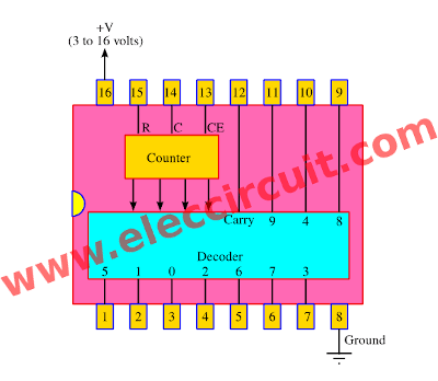
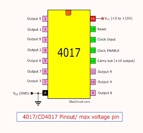
The CD4017’s pinout and function of each pin.
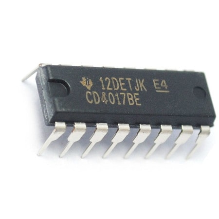
Thanks: Photo CD4017 Buy now
Detailed function of each pin
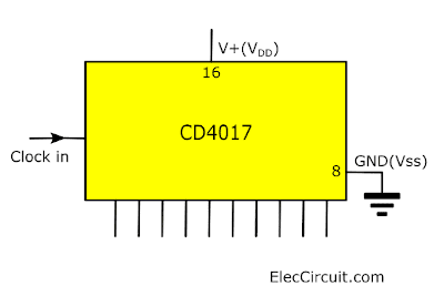
1.) Pin 16 is a positive power supply and pin 8 is a ground.
The power supply ranges from 3 volts to 16 volts. And Maximum power supply voltage must not exceed 18 volts.
2.) Pin 13 is the Clock Enable pin used to control the clock.
- When it is “0” logic, the clock will get enabled, and the counter advances one count for each clock pulse.
- But when “1” logic, the clock input is stopped, and the counter will do nothing even when a clock pulse arrives.
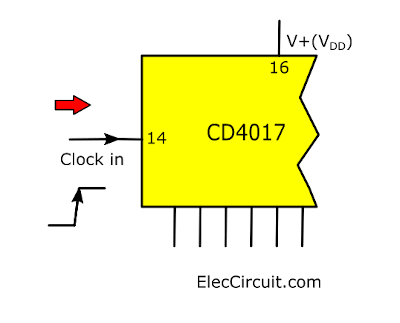
3.) Pin 14 is the clock input to trigger one count.
The clock pulse must be “clean”.
If they are “noisy” the counter may advance two or more times during each clock pulse.
The counter will count on the positive-going clock signal.
4.) Pin 15 is the reset pin. Normally, it is “0” logic.
When made “1” logic, the counter is reset to “0”.
5.) Pins 1-7 and 9-11 are the decoded output pins.
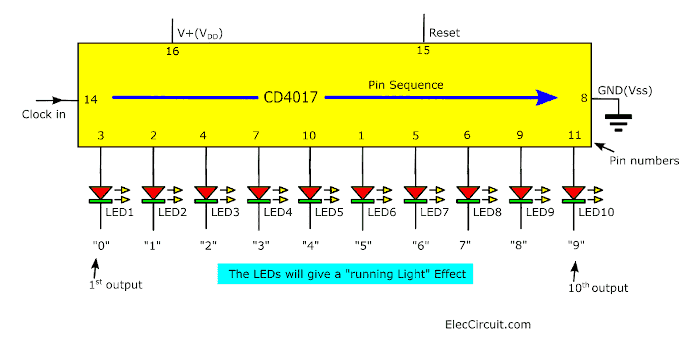
If a single output pin is “High” the rest will remain at “Low”.
LED1 is located at the first output that is labeled as “0”, this labeling process will come in handy later when we use this IC as a number counter.
When the counter goes up to “9”, it will loop back to “0” once again.
6.) Pin 12 is the carry-out pin, that “carries out” the clock input to an additional counter or an external circuit to continue the counting onward.
Working of CD4017
Here is the working process of CD4017 that might help you understand it better, and its explanation.
Meet basic frequency divider
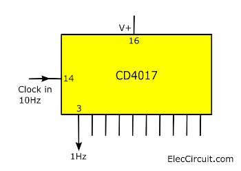
If we feed a frequency of 10Hz to the input pin 14. It will be equally divided between the 10 outputs.
The first output or any other output can only change its position once per second.
Since the Clock-In frequency of this chip gets divided by 10. Thus, most of the time CD4017 is called a decade counter/divider.
The dividing number can be changed to other values. For example, divided by 5, etc. Continue the reading below.
Output Buffer
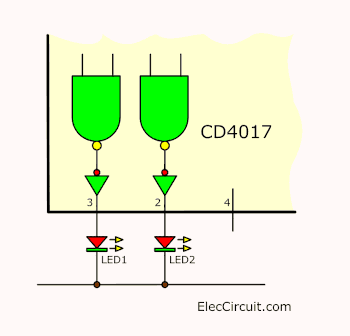
Each and every output of 4017 has a buffer able to drive a LED.
It also works as a gate to isolate the internal parts (NAND gate and others) from an external circuit. With, this working process helps the IC work with greater efficiency.
Control Pins
The counter circuit has 2 other important pins:
- Reset
- Clock ENABLE (Clock inhibit)
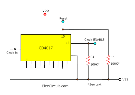
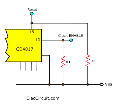
They are the control pins. We must connect them to either “high” or “low”. We can not leave them floating. This only applies to the reset & clock inhibit pins.
Reset Pin
First, when the reset pin connects to “low” or Vss. This IC will count the full 10 outputs.
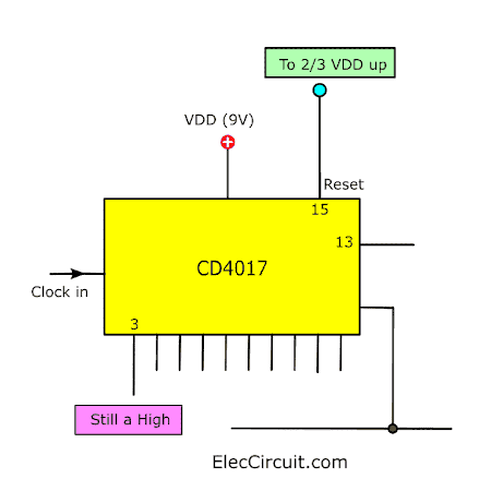
But if we fed them with a voltage of more than 2/3 of VDD, 6V in this case. Or a pulse of short duration into the reset pin.
It will always reset the counting process to the first state (pin number 3).
If we keep the reset pin “high”, the counter will stay still at the starting point (pin 3).
Clock ENABLE pin
Second, when we connect the Clock Enable pin (clock inhibit) to the “Low” state. The IC will count the full 10 outputs. As shown above.
In contrast, we connect it to a “high” state. The counter will pause on the output it currently counting.
Thus, we often connect pin 13 to the ground.
Make control pins stable
We should add R1 and R2, each resistor has 100K to 1M resistances, to keep the voltage spikes from entering the control pins.
Usually, the control pins a high impedance. It may get some unwanted noise from outside. If we connected R1 and R2 resistors from both control pins to the ground, to reduce their impedance. This means a lower chance of getting noise.
N frequency divider
If you want to divide frequencies with a number lower than 10. We can use CD4017 as below.
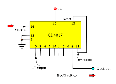
Divided by 9
We connect the output number 10 to the reset pin. This will make the counter count to 9 then reset.
Are you get ideas? See next…
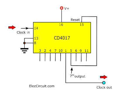
Divide-by-six Circuit
Then, we connect 7th output to the pin 15 (reset). Also, it will the counter count to 6 then reset.
Divide-by-N
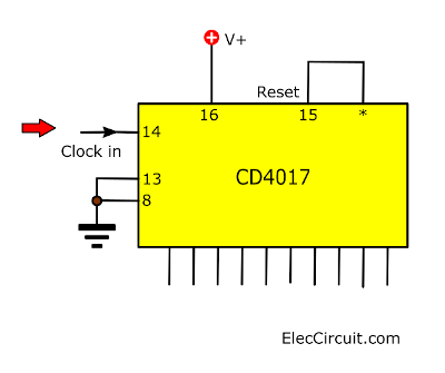
A divide-by-N. circuit for the CD4017 requires the N + 1 Output to be connected to the reset pin.
This circuit is helpful for add divisions or for a circuit requiring easy alteration.
A divide-by-N. circuit for the CD4017 requires the N + 1 Output to be connected to the reset pin.
This circuit is helpful for add divisions or for a circuit requiring easy alteration.
For standard division, a number of cheaper and better IC’s are available.
Read also, you will get more ideas
Do you love it? Read next…
How to Cascade the 4017 counter
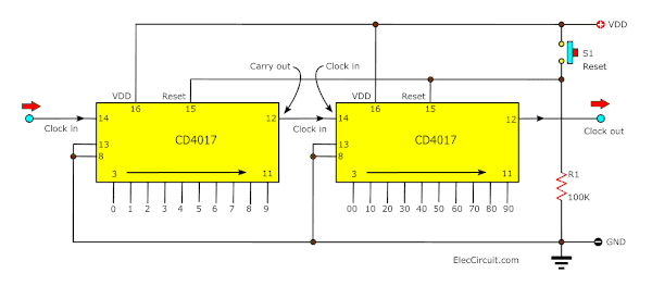
We can cascade two (or more) 4017 counters to produce a counter. See the circuit diagram, we use two 4017.
Ideally, it can be a pre-set counter in which the outputs are diode gated to a signaling device such as a lamp or bell.
We arranged the circuit to create a forward reading display and any number of chips. And we can add to increase the range.
Then, the carry-out pin 12 connects to the clock in the next counter. And, the reset and clock inhibit pins must connect to ground (Vss).
The advantage of including the 100K resistors allows a simple push-to-make switch. To control in the circuit for “reset” or “freeze”
Other equivalents IC of CD4017
Sometimes you may find this IC number, but with an extra character in the front or back. For example, CD4017BE, TC4017, MC14017, HCF4017, HEF4017, etc.
Most likely, the naming scheme is up to the manufacturer. But if the pin and function are the same you can use them instead of one another. Recommend buying the cheaper one.
Alternatives of 4017 are as follows:
- IC-4060 — 14-Stage Ripple-Carry Counters/Dividers with Oscillators
- IC-4020 — Binary Ripple Counter/Dividers, 14-Stage with oscillators
- IC-4040 — 12-Stage Ripple-Carry Counters/Dividers
- IC-4022 — Divide by 8 Counter IC
They also are a counter types ICs. But with a slight change in pin function, that might be adaptable in some usages.
For example, 15 basic circuits using CD4017
In addition to learning it through the CD4017 datasheet to some extent, we will also look at an example circuit that uses it to gain a clearer understanding of its use.
10 LED Flashing using IC-4017
This the circuit diagram of light LED flashing with a show of 10 LED.
By using integrated number circuit CD4017 perform be Decade Counter/Divider with 10 Decoded Outputs.
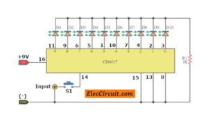
Which, it is an integrated digital circuit CMOS. Then, use the 9V power supply.
For a signal input continue the circuit can produce general frequency may use IC NE555 all right.
LED Chaser circuit using 555 and 4017
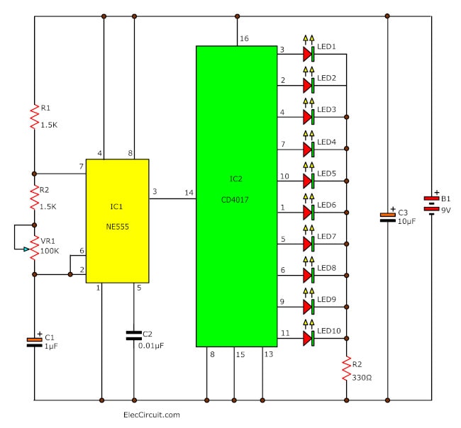
If you would like to learn basic digital. But it is difficult and boring.
Let’s try to create an LED chaser circuit. It used in computer games and in many scientific and mathematics applications.
So it is best for a beginner or for kids to learn digital.
Also, my son loves them. Continue Reading
Two way 12 LED running lights using 4017
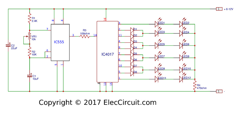
If you want a new style or beautiful lighting. The project may be good choice of yours. This is a two ways of LED running lighting.
Which it is one of the 4017 project that uses 12 LED lamps, arranged in 2 rows, each row of 6 LEDs. A green one and a red one, alternatively. You can use a different color for this.
Continue Reading To Look at more detail.
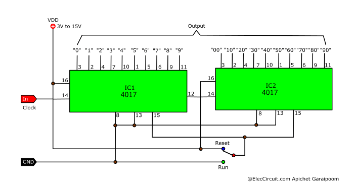
0-99 counter using 2x LM4017 IC
When you want the counter circuit from 0 to arrive at 99. I think this circuit may on the same wavelength you certainly.
It uses an LM4017 decade counter/divider as a circuit diagram below.
When we feed a signal clock at 14 pins. It causes the position logic at a pin output. From 0 to 99.
For switch, S1 perform choose RUN or Reset.
Please see the circuit picture will understand increasingly.
Almost forget integrated number this circuit, requires low voltage 3V to 15V power supply. Because it is IC digital CMOS.
10 Key Code Lock Switch Circuit

Simple Keycode lock switch circuit using IC-4017 digital uses 10 switch bottom to control output by Relay. No microcontroller is so easier and cheaper! Continue Reading
1 Hz Timebase circuit using IC-4017
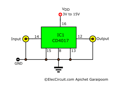
When we need a standard digital clock 1 Hz. but we have the input signal is square waveform 10 Hz so need to reduct it lower with digital frequency divider circuit 10 times
I suggest that IC 4017 (Decade Counter / Divider with 10 Decoded)
Bicycle distance meter circuit using 4N26, CD4017
With this circuit, you can measure the distance by using a bicycle wheel.
It includes a few parts, normal electronic circuits. And, has the important parts are reed switch detect a magnetic force to CD4017.
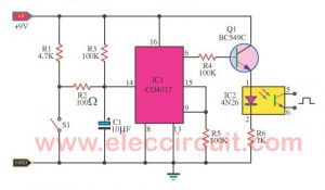
It is a Decade counter with 10 decoded outputs IC.
Then connected to Optocoupler 4N26, and display to a frequency counter.
2 Coin toss Game circuits diagram
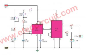
Press Switch-S1 you will see LED blink alternately. When release S1 LED will stop show Coin or Toss.
Automatic Day Indicator Circuit
This is the Automatic day indicator circuit, by LED display each day one by one LED.
Which uses the principal of light-activated in a day with sun. To set an LDR-sensor and CD4017 acts as drive LED of 7 pcs for 7 days there.
Electronic dice circuit using CD4017
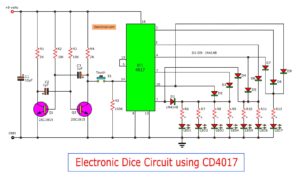
Which looks like real dice. We use only the press switch being thrown. With 6 LED Display.
10 LED roulette circuits using TC4011-LM4017

They use the principles of digital ICs. Create an integrated LED flashing to the rhythm. And then stopped at one of the LEDs.
Enjoy creating a game. And knowledge From digital ICs.
555 Sound effect generator circuit
This circuit would be a good starting point to composed music for 1000 tracks.
We will use an IC-555 timer and IC-4017 Decade Counter Divider with 10 Decoded.
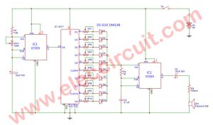
And has the sound effect generator with adjusting tone music with a tempo slow-fast as you want it to VR11.
And VR1-VR10 to adjust the tone according to need more than 1000 tone.
LED Dancing light circuit with Music
The main features are running light by changing the voice of the tiny microphone.
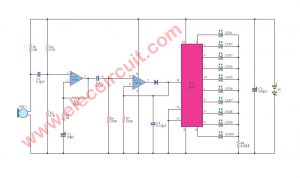
In the circuit, we use 4017 to drive 10 LED display. And, LM358 is a preamplifier and signal converter. With a few general devices.
Besides 4017 on my website. You can also see more.
Learn more Datasheet
CD4017 – A Decade Counter with Decoded Output
Which is better? Which circuit do you like to build?
Have fun with the IC-4017.
GET UPDATE VIA EMAIL
I always try to make Electronics Learning Easy.
Related Posts

I love electronics. I have been learning about them through creating simple electronic circuits or small projects. And now I am also having my children do the same. Nevertheless, I hope you found the experiences we shared on this site useful and fulfilling.

Extraordinário……
For the 10 LED Flashing Circuit Using IC 4017, there are three connections at the bottom right of the schematic, from right to left numbered 8 and 13. The next one is not numbered. What pin is it connected to?
Pin 15.
The connections for the LED’s are shown to start at pin #0. My IC doesn’t have a ‘zero’ pin. The pins start with #1 at the upper left of the 4017, with the first pin being #1, then going down the side to pin #8, and continuing up the other side to pin #16. The connection I question is for D10 and is shown as connection 3. What is pin zero?
Hi,
It does not have pin 0. The zero is the starting step of this IC.
Hello,
Please replacement 10th output name to pin 11.
3 pics have mistake.
Thank you..
Hello Name,
Thanks for your feedback. You are a great man.
You are a very observant electronicist. Thanks for the advice.
I have already fixed it.
If there are any other suggestions I was very pleased.
Thanks again,
Apichet
خیلی اموزنده وکاربردی هست مرسی که هستی
Hello Rostamnoei
Thanks for your feedback.
I would like a reset to the 0 to 99 counter circuit that you have shown in this article.
I need to reset the counter reaches the last of the cycle and then start again with the counter again. my telephone number is 913-963-6954. Thank you for your help.
where can I share my circuit for a problem query?
Hello,
You can just leave a comment on a related post.