This car led flashing lights project is installed in automotives, to modify brake light flasher circuit. Using a small number of pieces of equipment, so it is easy to build, consists of CMOS IC and power transistors, etc.
The rear brake light is warning lights to the behind car. Add Caution while tracking. This flashing brake light to sensitive drivers who tracking behind. Can be visible as far add to secure than a plain brake light. Which it will flash when a brake is touched only.
How it works
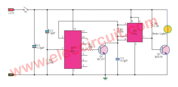
In the circuit is modification flashing to the brake light. The working start with the power to circuit or touch that brake. The timer-IC2 is driver current to transistors feed a clock signal pulse out to pin 3 go to pin1 of IC1, count amount of pulse and will stop counting when full 8 pulses. By pin 2 of IC1 will reset itself.
The transistor-Q1 is a trigger to IC2 and also results in pin 3 of the IC2 reverse stage, by getting a voltage drop across R3 cause have output voltage at pin 7 of IC2 cause Q2 receive forward bias to drive current cause the brake lamp glow up.
The flashing of bake light while touch bake Hold it, Will flash continuously per set around 6 times per second. Which defines by the R3 and value C3. The distance of each series is determined by the C2 and R1. The voltage that feeds to the circuit can use DC 12 volts of Car. The capacitors-C1 is a filter to smooth the currents. The transistors-Q2 may use any number SM3180.
Learn: How does NE555 timer circuit work
How to build it
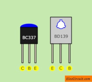
We can assemble all components on the universal PCB board. The wiring for circuit wiring and various components. So, be careful about the polarity of the electrolytic capacitors and Diodes correctly, Pin of the IC is not an error. And pin of transistors (BC337 and BD139) you can look at the image below.
Components List
Resistors size ¼W +5%
R1, R2: 10K
R3: 1M
R4: 1.2K
Capacitors
C1: 3.3uF 25V, Electrolyte
C2: 1uF 25V, Electrolyte
C3: 0.1uF 50V, Polyester
Semiconductors
Q1: BC337, 50V 800mA NPN Transistor
Q2: BD139, SM3180
IC1: CD4024, 7-Stage Ripple-Carry Binary Counter
IC2: LM7555, CMOS Timer
Others
Universal PCB Board
Recommended: 1.5V 4 LEDs Flasher circuit using transistors
Not only that. Look:
Beautiful Car brake light circuit using BC327
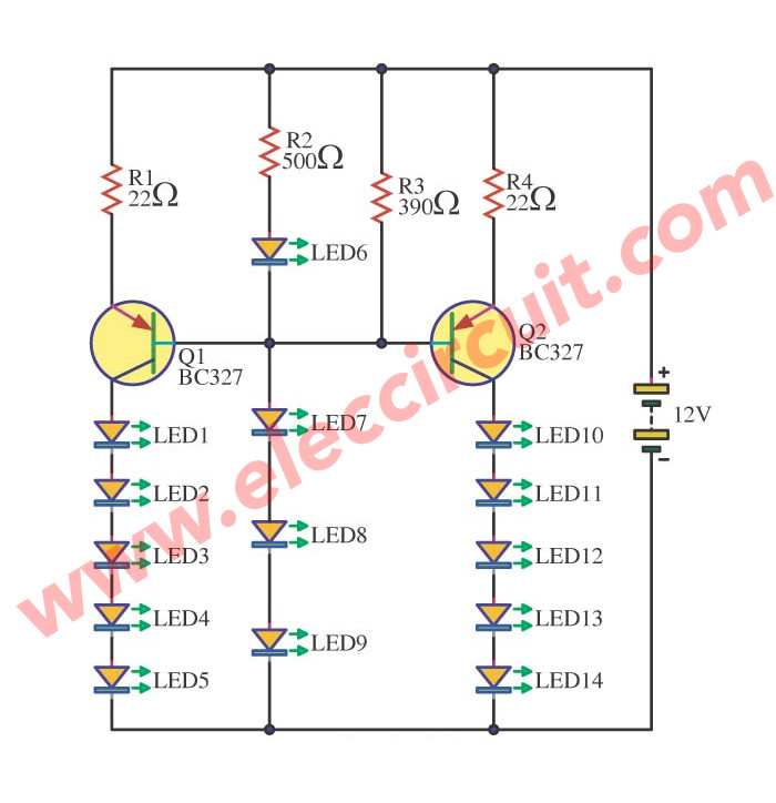
We will add beauty to CAR brake light circuit. With a display of 14 LEDs, visible clearly, for safety and beautiful. The installation format can fix by oneself as you like it. This circuit use the astable multivibrator for generate a oscillate frequency so all LED flashing.
The working of the circuits
Figure 1 : CAR brake light circuit
When enter the light brake voltage, makes have power supply 12V come in cause LED6-LED9 glow or On. Besides the trend will flow to change R2 go to bias pin base of Q1-BC327 PNP transistor and Q2-BC327, causes LED1-LED5 and LED11-LED14 the bright up. Which there are R1 and R3 help to limit a current that flow through LEDs enough liberate brake power supply 12V disappear make LED every switch off.
The components list.
Q1,Q2: BC327: 50V 1A PNP transistorrs
LED1-LED14: LED display as you want.
R1,R4: 22 ohms 0.5 watts 5% resistors
R2: 390 ohms, 0.5 watts 5% resistors
R3: 500 ohms, 0.5 watts 5% resistors
20 LED Rear Bike Light Flasher circuit using 555
This is 20 LED Rear Bike Light Flasher circuit using 555. Currently, traffic is convenient. The road is in good condition. Causing the car to run at higher speeds.
Cycling is so more dangerous. Especially at night. Even if there is a reflector attached to the back of the bicycle. But may not be visible.
A good solution is to create a bicycle taillight or a bike tail LED light flasher. It is Bike Blinking Safety.
It is easy that buy it in amazon.com But who are us? Electronic inventor, Right? Take time to create it better. Learning is always worth.
Imagine we just learn the 555 timer. We want to use it and a lot of super bright LEDs.
Read also: DIY Flashing Bicycle LED Taillight Circuit
Operation of the circuit
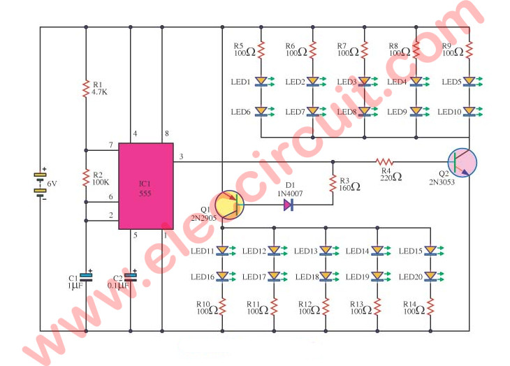
See int the circuit diagram.
Use NE555 is Oscillator to produce an output signal out of at pin 3.
Which output frequency determined by R1, R2, C1.
And the output is a square waveform.
When it is high voltage. It goes to pin B of Q2. And the Q2(NPN transistor) runs. Make LED1 to LED10 lights up.
However, if the output signal is “low”. And, the voltage is 0 volts.
No voltage to bias Q2. It does not work.
Recommended: How does NE555 timer circuit works
In contrast, the Q1(PNP transistor) will work. To drive LED11-LED20 are bright up.
Then, the high voltage comes again. Q2 and these LED1-LED10 run again too. Both sets of LED lights will blink alternately
We may use battery AAx4 (1.5V x 4 = 6 Volts). Makes can use a long time than 3 months. When using 3 hours every day. Or we can AC dynamo as a power supply source.
It is a good idea for saving money to buy the battery and reduce Chemical waste. But must have DC regulate as well.
You may also like these:
- Mini emergency light circuits
- 24 LED Decorative light circuit using NOT Gate
- How to make fast blinking lights for bike
- LED Dancing light circuit with Music
- LED Flashers Circuits and Projects using transistor
Parts you will need
IC1: 555 timer
LED1-LED20: LED as you want
C1: 1uF 50V Electrolytic
C2: 0.1uF 50V Ceramic
Q1: 2N2905,IC=0.6A, VCE=40V PNP Transistor
Q2: 2N3053,IC=0.6A, VCE=40V NPN Transistor
0.5W Resistors, 5% Tolerance
R1: 4.7K
R2: 100K
R3: 150 ohms
R4: 220 ohms
R5-R14: 100 ohms
Bike tail LED light flasher »
GET UPDATE VIA EMAIL
I always try to make Electronics Learning Easy.
Related Posts
I love electronic circuit. I will collect a lot circuit electronic for teach my son and are useful for everyone.


the website eleccircuit very gode
I can’t read the IC numbers on the bright pink background of many of your circuits. Many descriptions do not include the part number. The circuit cannot be built without this information.
Please could someone help me to make my car third brake light that use leds give a puls and then stay on until brake pedal is relesead.
thank you………..
Which type of switch u have used here? .and can u help me to name the switch which can be sensed automatically while applying brake
Hall. Pedal off foot out light goes.
Does this project works in motorcycle (bajaj pulsar 220 or 180) tail light? which is also LED tail lamp.
Hi, thank you for the circuit it works fine. In addition, what I want to ask is is it possible to increase the number of blows?
Hi,
Do you mean increasing the number of light bulbs?
If that is what you mean, you can add more light bulbs by changing the transistor to a bigger one. For example, TIP3055, 2N3055, etc.
God bless you.