LM741 is a very common general-purpose operational amplifier IC used in many kinds of circuits; you might have already used one before.
However, this article will provide more information about the LM741 OP-AMP, its features, typical configurations, and some example circuits.
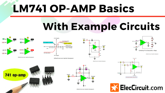
The LM741, LM741A, and LM741C—and their application-specific relative, µA741 or HA1741—are in the 741 series of operational amplifiers. They offer great performance compared to other OP-AMP ICs. Furthermore, they come with overload protection, which makes them easier and safer to use.
The LM741 Chip
It is a relatively advanced integrated circuit packed in a plastic eight-pin DIP-8 package. The LM741 has also been around for some time now but remains popular.
Plus, it also has an affordable price comparable to a transistor, which adds to its popularity.
General Features
The basic feature of an amplifier is that it takes an AC or DC input and amplifies the signal to a higher level at the output. However, the LM741 OP-AMP also has the following basic features:
- Overload protection—protects both the input and the output of the chip.
- Latch-up prevention—allows the chip to operate smoothly without having to power it off and on.
- Open- and closed-loop modes—LM741 can operate in open-loop configuration for higher gain or with a feedback network.
Are you a beginner? Learn Basic Electronics
Specifications of 741 OP-AMP
- Supply voltage range: ±5V to ±18V
- Input offset voltage: 2mV to 6mV
- Input Impedance: 300KΩ to 2MΩ
- Power consumption: 50mW to 85mW
- Supply current: 1.7mA to 2.8mA
- Power Dissipation: 0.5W
- Differential input voltage:±30V
- Max Input voltage:±15V
(should not exceed the power supply voltage) - Output short circuit time: none
- Operating temperature: 0 to 70°C
- Voltage Gain: 20,000 to 200,000
- Input offset voltage: 2mV to 6mV
- Input Impedance: 300KΩ to 2MΩ
- Bandwidth: 500KHz to 1.5MHz
- Slew rate: 0.5V per uS
Note that each of the variants of 741 chips, LM741, LM741A, LM741C, or even uA741, has different minor specifications. Therefore, if you are planning to use one in your project, please refer to the specific datasheet here.
Pinouts
As mentioned, the LM741 has eight pins; however, only five of those pins are typically used: positive and negative supply, non- and inverting input, and one output. This is reflected in its schematic symbol as shown below.
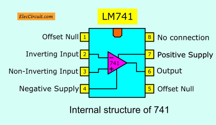
- Pin 1—Offset null
- Pin 2—Inverting input
- Pin 3—Non-Inverting input
- Pin 4—Negative Supply
- Pin 5—No connection
- Pin 6—Output
- Pin 7—Positive Supply
- Pin 8—Offset null
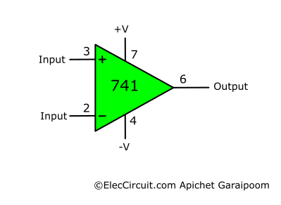
The LM741 in a schematic drawing is most often this triangular OP-AMP symbol. It is simpler than the full DIP-8 depiction while still containing most of the pins we usually use, and it is laid out in an easy-to-understand way.
The Power Supply
An OP-AMP usually requires a dual-polarity power supply to operate; for the LM741, it is recommended for a 4.5V to 18V power supply. For long-term uses, you should use a proper dual-polarity power supply such as 7805-7905 dual regulator circuit or these.
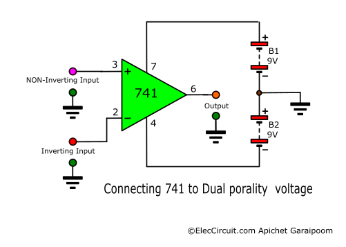
However, using two 9V batteries together as shown below also works as a temporary solution while experimenting. But in saying that, the LM741 has a very low power consumption, so using battery power long-term is not much of an issue.
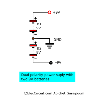
Then simply connect the power supply to the OP-AMP as shown below, +9V to pin 7 and -9V to pin 4. The difference between the positive and negative power also determines the range of the output, which we will talk more about later.
Type of OP-AMP Configurations
There are many ways to configure an amplifier with the LM741. We will only cover the few types we often use, and they might also be useful to you.
However, if you have any amplifiers you would like to learn more about, then feel free to leave a comment below, and we will try our best to cover them. Anyhow, here are three of the common LM741 amplifier configurations.
Differential Amplifier
Let’s start with the differential amplifier since it is a base for many other amplifiers. As the name may suggest, it amplifies the voltage difference between the two inputs by some gain.
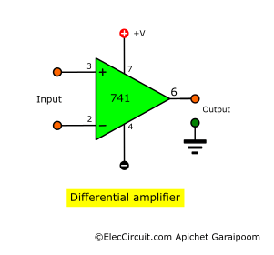
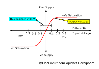
The graph below shows the relation between the inputs and output of a differential amplifier.
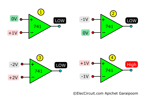
If both inputs have the same voltage, meaning there is no voltage difference, the output will be 0V. However, the output voltage will be HIGH when the positive input receives a higher voltage than the negative.
This is also true the other way around, the output will be LOW when the negative input has a higher voltage than the positive one. In summary: higher positive input means positive output; higher negative input means negative output, as shown here:
The graph shows that the voltage difference required for the output to swing from lowest to highest is 200μV. If you recall, we are using two 9V batteries as a power supply; this means that the output voltage swing range is 18V, with a minimum of -9V and a maximum of 9V.
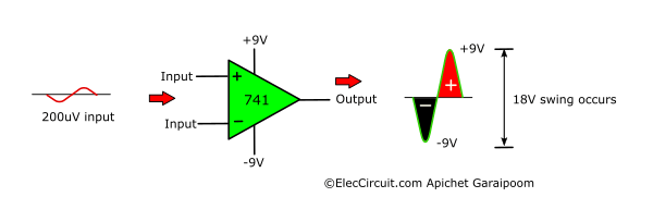
In this case, the OP-AMP operates in a linear range, which means that a small change in input influences a bigger change in output. So, if the positive input is within 200μV higher than the negative input, the output will be in a HIGH state and have a positive voltage proportional to the voltage difference between the two inputs.

However, suppose the negative input is within 200μV higher than the positive input. In that case, the output will be in a LOW state and have a negative voltage proportional to the voltage difference between the two inputs.

Inverting Amplifier
An inverting amplifier uses a similar idea to the differential amplifier but without the input voltage difference parts. The positive input, or the non-inverting pin, connects to the ground and acts as a reference point for the negative input.
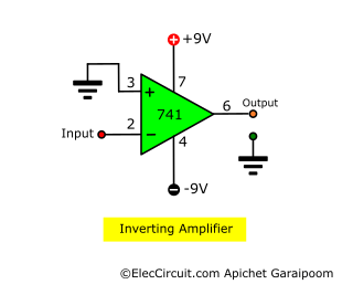
When voltage is applied to the negative input, the output changes inversely and proportionally to it.
Non-inverting Amplifier
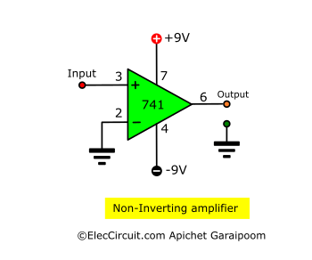
A non-inverting amplifier, on the other hand, amplifies the input signal proportional to the gain without inverting it. In a non-inverting configuration, the negative input, or the inverting pin, is connected to the ground instead.
Using a Single Power Supply
The OP-AMP—in this case, the LM741—can also operate from a single power supply, as shown below. This reduces circuit complexity by eliminating the need for a dual-polarity power supply.
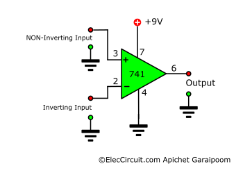
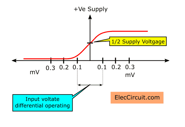
However, because of the lack of a negative rail, the point at which there is no difference in input voltage shifts up from 0V to the ½ point of the supply voltage instead. The swing range remains the same at 200μV. Therefore, depending on the situation, using a single power supply may not be feasible.
Recommended: How to use op-amp in the power supply
Thanks to the Wise Cr: Learn op-amp working as power supply on the Talking Electronics No.9 page 25 to 29
Examples of LM741 Circuits
Throughout the years, I have collected many small LM741 amplifier circuits, both for use in actual applications and as inspiration for future projects.
The list I compiled below includes the majority of the circuit types I frequently see, and, despite their age, many of them are still applicable today.
Inverting Amplifier Circuit Using LM741
This circuit is a practical implementation of the inverting amplifier we mentioned earlier. Its core function remains the same; the output is amplified inversely to the input.
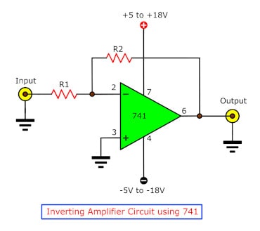
The two components are resistors, the resistance of which controls the gain of the amplifier. We can see their relation clearly through the following formula:
Non-Inverting Amplifier Circuit Using LM741
Similar to the inverting amplifier circuit above, this is a functional version of the non-inverting amplifier. It amplifies the input to the output but does not invert the signal.
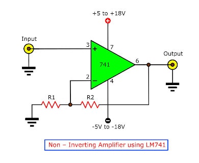
The two resistors work similarly to the one in the inverting amplifier. However, as the circuit does not invert the input, we use a different formula to calculate the output:
Basic Summing Amplifier Circuit Using LM741
The summing amplifier is another handy amplifier circuit. As the name may suggest, it will output the sum of multiple inputs. But since this circuit is in an inverting amplifier mode, it will output the negative of that sum.
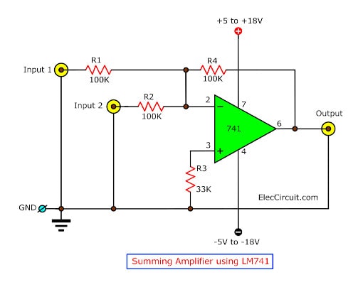
This means we could combine multiple voltage inputs. However, the example circuit here has only two inputs, and its output is as follows:
When R1 = R2, but not R4:
Whereas when R1 = R2 = R4:
An audio mixer, for example, is an excellent application for a summing amplifier, which sums multiple sounds from different channels before sending the signal to another amplifier circuit.
You can read about Summing Amplifier HERE.
Clipping Amplifier using LM741
An inverted clipper, or clipping amplifier, limits the peak voltages in a signal. It effectively slices a part of the waveform close to the positive and negative voltage peaks. A clipper is often used in audio amplifiers to reduce high peaks and transform sine waves into square waves.
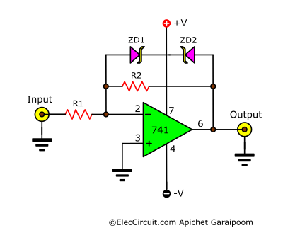
The breakdown voltage of ZD1 and ZD2 Zener diodes determines how much of the input signal is clipped. The output voltage is calculated using the same formula as an inverting amplifier, that is:
Note that the output voltage should be lower than the two Zener diodes’ breakdown voltage plus 0.7V. For instance, if ZD1 and ZD2 are 6V, the output voltage should not exceed ±6.7V.
Basic Inverting Integrator Using LM741
An inverting integrator integrates the input signal over its amplitude. It is often used to convert a square wave to a triangle wave signal or low-pass filter.
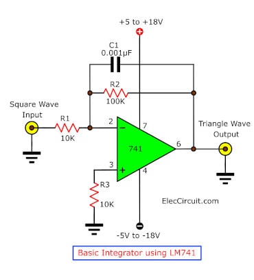
It functions the opposite of a differentiator amplifier, which takes the derivative of the input signal. An integrator outputs a voltage proportional to the integrated value of the input signal.
Basic Single Polarity Supply Amplifier Circuit
This single-polarity supply amplifier circuit converts negative input voltage to positive output voltage. It uses the inverting amplifier configuration and only a positive power supply to do so.
The LM741’s pin 4 negative supply is connected to the ground, meaning it only uses a positive power supply. When the input is negative, the output will be positive; whereas when the input is positive, the output will stay at zero.
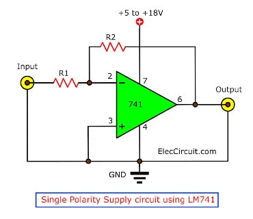
R1 and R2 can be changed for any gain. We could also adapt this circuit to a negative output, converting a positive voltage to a negative voltage.
Read next: Universal Preamplifiers using | NE5532 | 741 | LM382
Unity Gain Follower Or Buffer Circuit Using LM741
A buffer circuit connects two circuits without loading or impedance factors. Its main characteristic is that it does not change the signal, meaning that its input and output are equal; it acts as a buffer between them.
Connecting a circuit with a high output impedance to a circuit with a lower input impedance could cause load issues. However, adding a buffer circuit in between them helps stop the issues while keeping the signal and voltage the same.
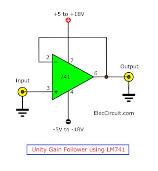
Without the resistors, this non-inverting amplifier always has a gain of 1, thus not affecting the signal. The input can be in any format with a frequency less than 1MHz. Also, we can set the output voltage limit with the power supply circuit, from ±5 to ±18V.
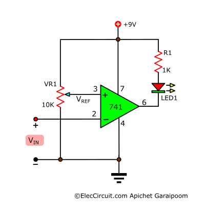
Simple Level Voltage Detector Circuit
VR1 is used to choose the reference voltage. If the input voltage exceeds the reference voltage, LED1 will light up. Vin should not be higher than the VCC, or 9V. Read more: 741 Level Voltage Detector
Simple Active Low Pass Filter Circuit
This circuit lets through signals with frequencies lower than its cutoff frequency while attenuating the rest. The cutoff frequency is determined by the capacitor and the resistor using the formula:
Where in this circuit R = R1 = R2 and C = C1 = C2.
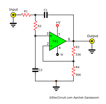
Since this circuit is quite interesting, we plan to write a detailed article about its workings and details soon.
Conclusion
The LM741 is an easy-to-use OP-AMP with enough quality to use at many levels, which is why it is very popular. An OP-AMP like the LM741 is still useful even in a complicated electronic circuit. The examples given are only some of the circuits; the LM741 could still be used in many different circuits. If you are interested in any circuit in particular, please share it with us.
Here are a few related posts you might want to read next:
- Automatic Night light circuit using LDR and IC-741
- Active bass booster circuit using 741
- Automatic Op-amp night light circuit using 741

Hi I would like to build voltage amplifier as weel as regulator using lm741. The input would be 0.05mv to 50volt. The input pulses per min would be 1-30000. The output pulse should be regulated 5 volt at all frequencies and voltage inputs. Plz if anyone could help me.
As a newbie in this field, this article is very practical for me. I hope to continue to update it!