Let’s use two simple Analog VU meter schematics. If we take the amplifier connected to the speakers. It is very dangerous.If your amplifier has a higher power than the limits of the speaker. It may make a very bad sound. More important is the speaker and amplifier may be damaged.These circuits may help you!
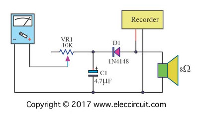
Simple Analog VU meter circuit

An expensive stereo is general often have built in VU meter to show max power (not too much). But a typical radio receiver or small amplifier will not have the VU METER.
I will modify the multimeter, or a galvanometer in the measuring range 100uA. And another small number of electronic devices.
In circuit,diodes and capacitors acting rectifier and filter from AC to DC current.
The VR1-Potentiometer 10K for fine full scale of meter
Easy to use, you build this circuit into internal monitor speakers right away.
Parts you will need
M1: 100uA Galvanometer or VU Meter
D1: 1N4148, 75V 150mA Diodes
C1: 47µF 25V Electrolytic Capacitors
VR1: 10K, Linear Potentiometer
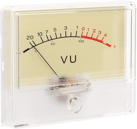
Thanks: Photo Amazon.com
Peak Reading VU Meter by IC CA3130
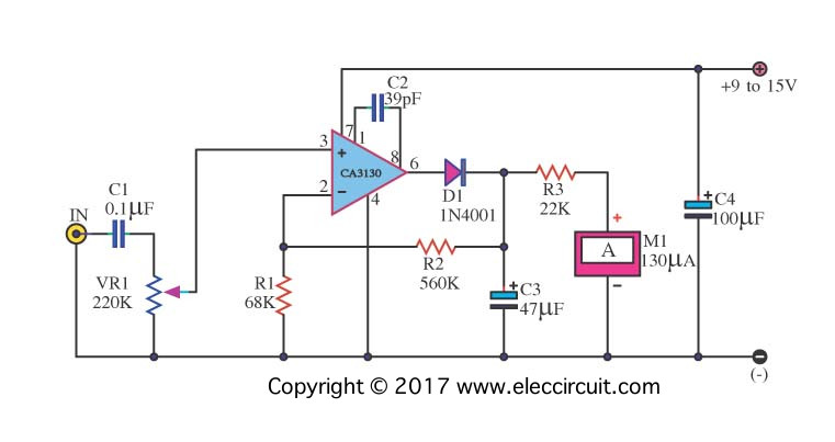
When you build Amplifier Circuit. You maybe need Peak Reading VU Meter circuits. I recommend this circuit, it uses IC CA3130 opamp, giving high sensitivity, indicating with a Current Meter (Standard VU-Meter unit). easy to build.
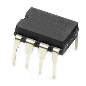
Thanks: Photo CA3130 Buy now
VR1 is used for fine adjustment of input signals. Also perfect unit for a audio signal mixer to adjust recording level.
Parts you will need
IC1: CA3130, Op Amp, BiMOS, MOSFET Inputs, CMOS Outputs, 15MHz
M1: 100uA or 130uA Galvanometer or VU Meter
D1: 1N4148, 75V 150mA Diodes
C1: 0.1uF 50V, Ceramic Capacitors or Polyester Capacitor
C2: 39pF 50V, Ceramic Capacitors
C3: 47µF 25V Electrolytic Capacitors
C4: 100µF 25V Electrolytic Capacitors
R1: 68K 1/4W Resistors tolerance: 5%
R2: 560K 1/4W Resistors tolerance: 5%
R3: 220K 1/4W Resistors tolerance: 5%
VR1: 220K___Linear Potentiometer
GET UPDATE VIA EMAIL
I always try to make Electronics Learning Easy.
Related Posts

I love electronics. I have been learning about them through creating simple electronic circuits or small projects. And now I am also having my children do the same. Nevertheless, I hope you found the experiences we shared on this site useful and fulfilling.
Shall I Use multi-meter or any other meter instead of VU meter???
this is a good project to build with is a little complicated to build.
Hi,
I would like to buy complete set for the 2 Vumeters (Parts and PCI boards). Please give to me the total price with shipping fee to:
Tran dai Phuc
21 rue de Lesigny
94440 Santeny. France
My email : [email protected]
Hello PhucTran Dai,
Thanks for visiting. I am sorry cannot sell these components to you.
But you purchase a product by affiliate Amazon links. https://amzn.to/3fApgaM
I receive a small commission – at no extra cost to you.
Very interesting , useful and important circuit for beginner.Many many thanks for your subject.
Hello Md Golam Rasul,
Thanks for your feedback. You are power for me.
Thanks