Today we are going to build a Simple Solar-Powered 12V Water Pump Circuit with Battery. We had recently built a cement fishpond at the end of the backyard. But the issue with these cement ponds is that the oxygen level in the water is quite low, which is dangerous for the fish.
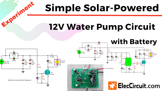
There are many ways to maintain the water’s oxygen level; in this case, we will use a water-circulating pump. However, because there are no outlets in the backyard, we would have to rely on a solar-powered DC pump and other inexpensive and readily available components.
Our Needs and Objectives
- Utilizing a DC water pump to circulate the water inside the pond, thus increasing its oxygen level.
- Using only an 18V 20W solar cell and a 12V 5Ah battery as a power source.
- Only works during the daytime, allowing the fish to rest at night.
- Uses cheap and easy-to-find components, or better yet, reuses or recycles existing components.
How It Works
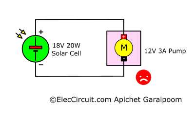
Looking at it as a big picture, the simplest form of the circuit is just a 12V 3A pump and an 18V 20W solar cell, with the former powered by the latter. However, if we were to actually connect both of them together, it would not work because the DC motor inside the pump requires almost three times as much current as the solar cell supply, which is 1.1A (20W ÷ 18V).
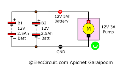
Another way to power the motor inside the pump is to use a battery. So we tried connecting it to a 12V 5Ah battery, and now the pump functions properly. We also add in another of the same batteries in parallel to increase the current they can supply by two times.
These batteries are then charged by the 18V 20W solar from earlier, which is very simple, as shown in the picture below. The two diodes are there to block a reverse current coming from the batteries.
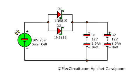
Both of the diodes used are 1N5819 Schottky barrier diodes. By itself, it can withstand up to 1A at 40V, but when connected together in parallel, they can withstand a current of 2A, which is sufficient to withstand the current from the solar cell.
Functions Only During the Daytime
From the circuit above, if we were to connect the DC pump to the battery, it would work continuously until the power ran out. But we only want it to work during the daytime. So the simplest way to do this is to add a relay to the circuit.
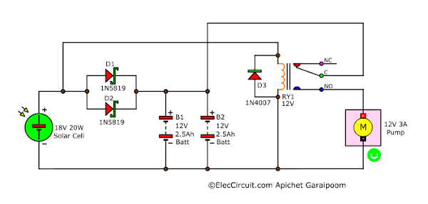
During the daytime, the current from the solar cell will flow through the relay coil, pulling contacts C and NO together. The current from the batteries will then be able to flow to the pump and power it on.
However, the downside of using a relay is that its contact needs to be large enough for the load, meaning that we would need a bigger relay, which can require up to 50mA to power its coil.
Even though I like using a relay like this because of its ease and affordability, if we want to remain with the old technology, it will be impossible for us to learn new things. So instead, we are going to learn how to use other newer components, such as a MOSFET.
It functions similarly to a relay in that it can switch large amounts of current efficiently. The difference is that it is a semiconductor, similar to a transistor, and thus lacks contacts, meaning that it will have better durability and responsiveness.
Note: In the future, we will learn more in depth about using a MOSFET as a switch. However, for the time being, we will only be covering the fundamentals.
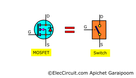
The MOSFET can function as a switch by controlling the voltage at G, allowing more current to flow through D and S. It may seem similar to the transistor, but the MOSFET uses voltage at G instead of the transistor’s base current.
In this case, we chose the IRF450 N-channel MOSFET, which is similar to a transistor but has a higher efficiency, giving it a maximum current it can withstand between D and S of up to 28A and a maximum voltage at D of 100V. However, between the D and S, there are around 0.077 ohms of resistance.
But the MOSFET has one important issue, which is that it is very sensitive to electrostatics. And since its G has a very high resistance, even an electrostatic with high voltage but low current can damage the MOSET through it.
Therefore, we should add a pull-down resistor between G and S. Also, to further boost confidence, we should add a parallel Zener diode to it to prevent the voltage between G and S from being too high. It is stated in the datasheet of the MOSFET that the Zener diode voltage must not be higher than 20V, so I think that 9V to 12V should be enough.
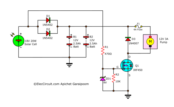
According to the circuit above, during the daytime, the current from the solar cell will flow through R1 to the G of the Q1-MOSFET, causing it to function like an ON switch or a relay. We also add a D3 to protect against the reverse current from the motor inside the pump, which may harm other components, and a fuse 4A to prevent the motor from drawing too much power.
As for the nighttime, no current flows through R1, thus the MOSFET does not function.
Read also: Small Automatic Plant Watering with a Solar Cell Power System
Working ON and OFF
Continuously working motors may generate high heat
We have a rice milling machine to mill our own rice. And we saw that if it works continuously for a few hours, it will shut itself down because of the heat generated. After it has cooled down, it will power back up again.
We should also add the same mechanism for the motor inside the pump.
Using the pump’s downtime to charge the battery.
Setting up a cooldown period leaves a time window to be used to charge the battery more effectively, as shown in the graph below.
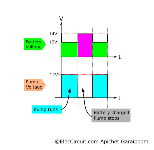
During the period in which the pump stops working, the charging current from the solar cell will flow to charge the batteries. Note that the batteries’ voltage will increase to 14V so that they can supply the pump when it starts back up again.
With this idea, we can try using the square wave oscillator circuit using the NE555 as an astable circuit to generate a square wave signal with a period of 146 seconds, or around 0.007 Hz, for both the ON and OFF periods.
We can determine the period, frequency, and duty cycle by choosing the values of R1, R2, and C1. The value of C1 is the most effective way to determine the period.
But in my experience, the NE555 is not suitable for long periods. Because the value of C1 must also be high, this may result in a large number of errors. However, if you want to try it, you can increase it to 1,000uF.
Apart from this, increasing the values of R1 and R2 can also increase the period further. But it might affect the duty cycle; in this case, we need around 50%.
You can learn more about it here: internal Link
Atlas, we combined this part with the circuit earlier to create a completed Simple Solar-Powered 12V Water Pump Circuit with Battery circuit, as shown below.
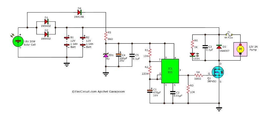
We did change a few things, including the position of the ZD1 and the addition of C4, C5, and R5, to keep the voltage from the solar cell supplying the IC1-NE555 at 9V during the day; at night, it will not supply any voltage as previously stated.
Also, add LED1 to indicate that the output is powering the pump and C3 to contain the transient noise from the pump running.
Want more brilliant ideas? Here’s how to get them through electronic circuits.
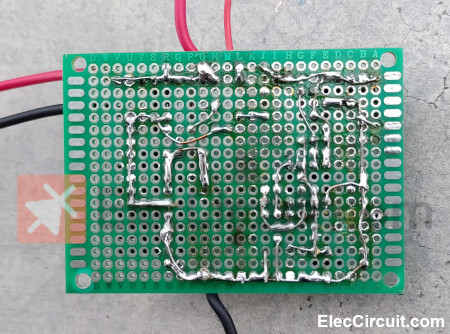
Building the Circuit
We have assembled this circuit on a perforated PCB, making it small and quick to build.
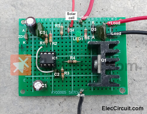
After finishing assembling the circuit, checking for any errors, and testing it thoroughly, we can conclude that it worked very well.
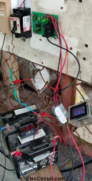
Note: In the testing of this circuit, we did not use the fuse F1 to protect against the pump consuming too much power. If the pump is consuming too much power, it may be damaged. So if you are planning to use it long-term, you should add a fuse as well.
Conclusion
The building of this circuit yielded very satisfying results. We have many choices, starting with the relay, which is the easiest and cheapest way. Next is using the MOSFET, which, although having higher efficiency, requires a lot of components. And lastly, we add to the circuit an interesting period timer function. In my opinion, if you have a large enough solar cell panel, you should go with the second circuit. It is the most balanced circuit in terms of price and complexity.
GET UPDATE VIA EMAIL
I always try to make Electronics Learning Easy.

Great Teacher. Thank you very much.
Hi,
Thank you for your feedback. Your message makes us smile.
My dad felt good about these contents being useful for you. 🙂
Ainda que não chegue a montar os circuitos apresentados aqui, adquiro um profundo conhecimento, mesmo já tendo dezenas de anos no ramos.
PARABENS!!!!!!!!
Thanks for your feedback. 🙂
could i use a 5ah battery instead of the 2, 2.5 ah?
Yes, you can.
Very nice design until you want the transistor IRF450, been a job on the web to get that!