If we were to use a DC water pump without an AC outlet, most likely we would power it with a 12V lead-acid battery. It is quite convenient, although their life span will shorten drastically down to around two years.
However, there are things that we can do to prevent this, which are also features of this simple DC pump protection circuit, namely:
- Protection against the wrong polarity of power.
- Reducing the power surge during pump startup.
- Shuts off if the battery’s voltage is too low.
- And most importantly, a simple circuit that allows us to learn about basic electronics.
Circuit Design and Choosing Components
Now, let’s put those sets of features into a simple block diagram, which will help us determine the order of operation of the circuit and find components for each function we need.
Main Block Diagram
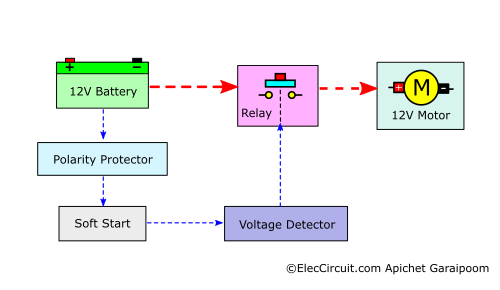
Polarity Protector
A traditional DC water pump (such as the one shown below) contains a DC motor as its main component. Which must be supplied with the proper voltage polarity; otherwise, the pump will malfunction or be damaged.
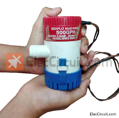
Preventing this is very easy; we simply need to add a diode at the input of the circuit, which we will discuss later.
Soft Start
When a motor powers on, it will consume a lot of electricity at first. For example, a 12V 2A DC motor may have a surge current of 5A. But after the motor shaft begins to rotate, it will consume less and less power until it stabilises at the rated 2A.
We should avoid this state. The simplest method is to use a relay instead of a normal on/off switch.
Because the relay includes contacts that can withstand a higher current than a small on/off switch, and it also has a relay coil that requires only a small amount of current to turn the relay contacts on and off.
Once here, we can easily test the soft start and polarity protector as shown in the circuit diagram below.
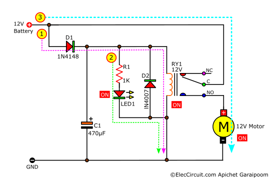
Its step-by-step working process is as follows:
(1) The D1 only allows positive voltage to flow into the circuit; thus, the circuit would not work if supplied with the wrong voltage. These positive voltages will then flow through the relay, turning it on.
(2) At the same time, the current also flows through the LED1, which indicates that the relay (RY1) is working.
(3) The rest of the current from the battery will then flow through contact C-NO to the DC motor.
Voltage Detector
The voltage of the 12V battery will continue to gradually decrease as it is consumed. In my experience, when the voltage drops below 11V, the DC pump will start to perform worse. So it is best to stop supplying power to the DC pump when that happens.
But how can we easily and accurately detect the drop in voltage? We chose the TL431 as a voltage detector because it is easy to use. Apart from this, according to the datasheet, they are used as voltage comparators, undervoltage monitors, overvoltage monitors, and window voltage detectors.
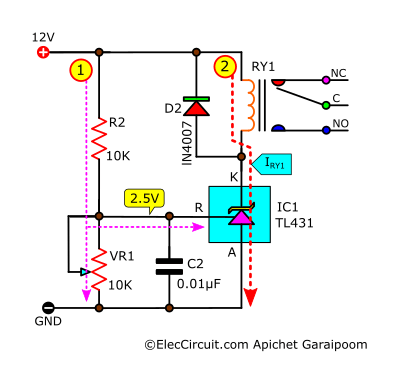
We can easily use the TL431 to detect voltage levels in a similar way to those of a normal transistor. If pin R detects 2.5V, it will allow a large current to flow through A to K, like a turn-on switch.
The R2 and VR1 are placed in series to form a voltage divider, which will lower the Vin to a more manageable 2.5V.
The C2 reduces noise from voltage spikes or transients that may occur.
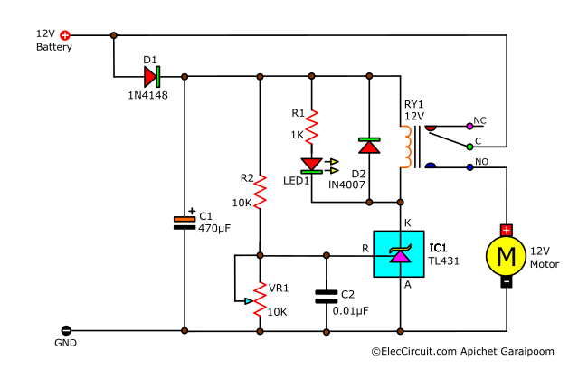
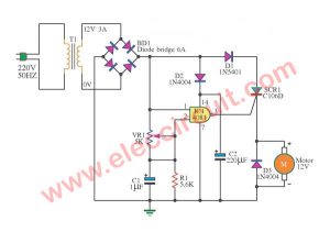
So now, if we put all the parts together, we will get the complete DC Pump Protection Circuit as shown below.
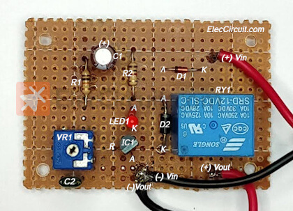
Building this circuit
My daughter has assembled this circuit on a perforated PCB, making it small and quite quick to build.

After we have assembled the circuit and made sure that there are no errors, we will move on to setting up the circuit as listed below:
- Make sure you are using an adjustable power supply that can supply more than 2A of current instead of a battery. Because the DC pump (load) requires 2A of current.
- Start by setting the power supply voltage to 11V, then adjust to VR1 until you hear a click from the relay, as this indicates that the relay is working as well as the pump.
- Then, gradually increasing the voltage of the power supply to 14V, the pump and the relay should still be working. Note: Be careful not to increase the voltage to more than 15V, as it might cause the pump to overwork.
- After that, try decreasing the voltage to something lower than 11V, such as 10.5V. We will hear a sound that indicates the relay has stopped working, cutting the power to the pump and thus turning it off.
If everything has gone according to the steps above, it means that the circuit is ready to be put to real work.
Conclusion
As we have been using this circuit for a while now, it has worked very well in extending the life of our battery and pump. Normally, batteries have a lifespan of about two years, but with this circuit, we can extend it to four or five years. In the future, we may adapt the TL431 and a circuit surrounding a pump to other applications as well. We hope that you will stay tuned.
GET UPDATE VIA EMAIL
I always try to make Electronics Learning Easy.
Related Posts


I love electronics. I have been learning about them through creating simple electronic circuits or small projects. And now I am also having my children do the same. Nevertheless, I hope you found the experiences we shared on this site useful and fulfilling.
Muito bom este circuito,ideia genial,vale a pena ver essas surpresas,valeu
Thank you for your feedback. We intend to learn electronics through this circuit. It will continue to be developed further.