This is a key code lock switch circuit, type of electronic circuit. To replace a conventional normal key switch, without inserts keys. But you can press the number code instead of unlocking keys.
We do not need to carry a load key, and do not worry about your keys are lost. We just must remember to commit to code only.
The feature of this circuit
- Using a four numeric code number and can change one thousand numbers.
- The case of other people to know our original code. The code can be changed easily.
- It is a simple digital circuit that without a microcontroller. Thus it is no programming, easiest, and cheaper.
The circuit is designed to have the reset system, immediately enter the wrong code. So can prevent pressing a random numeric code. Because in this circuit the switches are set to the ten numbers, be the code switch 4 pcs. and be reset switches 6 pcs.
The advantages of having a system reset. Suppose we set the code number is 6583. If people do not know the code, they will press random from 0 to 9. It will have one correct number is 6.
But we press randomly in second, that is not 5. Then, the circuit will reset number 6 that last remember go away.
Thus, we will enter a correct code, just the first digit only. However, if it is without the reset system. Even those who do not know the code, it can press random in a fourth only.
When we hit 0-9 from the first round, we will correctly hit to the No.6. Then we hit the second round will correctly is one of No.5 as well. When the full four rounds, it will have a four code so the circuit is working.
This difference is quite obvious.
We have talked about its advantage and disadvantages for enough. Then to look at the circuit and how it works really well.
How it works
This circuit uses a 74HC4017 or CD4017 IC number that is DECODE Counter model. It serves to change the code.
In normal conditions, when we provide a power supply to this circuit. Then, there is a positive voltage at the output, pin 3 of IC1.
When you press the switch A, S1. The positive voltage from pin 3 via it to pin 14 of IC1, input pin.
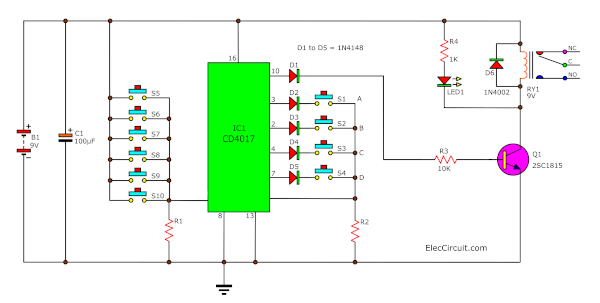
Key code lock switch circuit diagram
Next, when IC1 has the input is a positive voltage. It will move the output from pin 3 to pin 2.
So the next switch that we must press to be switch B, S2. It causes the positive voltage at the input of IC1, in the next step.
As you can see, if we do not press switch B, it will not change any more of IC.
And if we push a wrong switch in one of six options on the left-hand side of this circuit.
It is the positive voltage to pass through this switch to the input pin 15, reset pin of IC1. When pin 15 is the positive voltage, IC1 will change the output to at pin 3.
Thus it is resetting switch A to restart new again.
If we press these switches in the correct ways from A, B, C, and D in order. IC will move output to pin 10. Which it connects through a diode, and R-10K to pin B of the Q1-2SC1815.
Then, Q1 conducts power to relay-RY1 and LED1, they work together. the LED lights up.
For Relay-RY1:
It acts like SPDT switches (Single-Pole, Double-throw). We normally press or rock, this switch, right? But now we are feeding the current coil of the relay. It will become electromagnetic sucking or plugging the switch contacts instead of our fingers. So it can control other loads.
Let us know, the 5 diodes that are connected to the out of IC1. They protect a collision of the output. For example, the two codes are the same as the 5385 code.
IC 555 inverter circuit using MOSFET
Automatic battery charger circuit
LM386 audio amplifier circuit with PCB
How to set the code on button keys
When we need any code, we can connect the code number to switch positions.
The order of the codes is not the order of the switches.
For example, we need code is 5387. We have to connect as follows.
- First, CODE 5 to Switch 1 (A) at pin 3 of IC1
- Second, CODE 3 to Switch 2 (B) at pin 2 of IC1
- Third, CODE 8 to Switch 3 (C) at pin 4 of IC1
- Fourth, CODE 7 to Switch 4 (D) at pin 7 of IC1
- Fifth, other CODEs to Switch 5 to 10, to connect to pins of IC1
Look at setting code diagram below.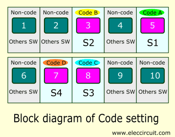
Parts List
IC1: 74HC4017 or CD4017 —DECODE Counter model
Q1: 2SC1815 or 2SC828 —45V 0.1A NPN Transistor
RY1: Relay 9V—One contact 5A
C1: 100uF 25V—Electrolytic
0.25W, 5% Resistor
R1,R2_100K
R3_10K
R4_1K
D1-D5_1N4148—0.4A 200V Diodes
D6_1N4002—1A 200V Diode
LED1_LED any color 3mm.
S1-S10_Switch Tactile ON OFF Single Pole, Single Throw Round Button
B1: 9V battery Or 9V power supply circuit
Keep reading: ‘16 key encoder using IC 74C922N’ »
How it builds
If you want to build this project, can assemble them on universal PCB. Because of fast and saving.
But you need to make the general PCB,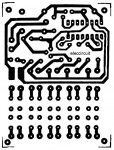
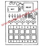
Actual-size of single-sided Copper PCB layout and
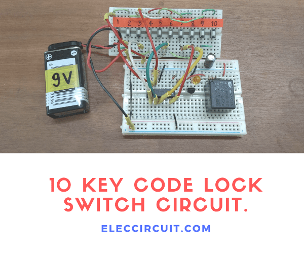
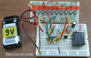
We test the circuit on a breadboard it working, as Figure 2
Watch video building and testing circuit on a breadboard.
Note:
The Q1, you can use a lot of numbers that are NPN transistors but the position legs are different.
Creation – Application
You should assemble include the parts in the correct place. The small first such as R, Diodes, IC Socket, etc. Then, followed by large parts.
When place parts ready, Check everything compete before, insert IC1 into a Socket. Next, connects a power supply, and press code. If the relay pulls in and the LED glows, the circuit works well.
Download This Post as a PDF and all PCB layouts
Keep reading: ‘One button code Switch’ »
GET UPDATE VIA EMAIL
I always try to make Electronics Learning Easy.
Related Posts

I love electronics. I have been learning about them through creating simple electronic circuits or small projects. And now I am also having my children do the same. Nevertheless, I hope you found the experiences we shared on this site useful and fulfilling.



I really like it when individuals get together and share thoughts.
Great website, keep it up!
How to change the code of this circuit
Hi, irfan shah
You can change position of A B C D of code to any Sw1-10 on panel.
Is this project work in real????
Bcs i got this project in my clg
Pls tell me and help me bcs i hv very short time to complete it
I will bw thank full you
is it really works? badly need in our project :'(
Boa tarde, como projeto de final de ano decidi elaborar este projeto do “switch key” e, tendo todos os componentes bem montados, não consigo fazer o circuito reagir, preciso de fazer alguma alteração?
Obrigado pela atenção,
Cláudio
There is only one but major problem in this project and that is “sequence of shifting the output from one to another is not trustworthy”. After providing clock pulse the shifting of output is not sequential. May be, this is fault of IC.
I have succeeded in making this project.
It is really a good project.
It is working also good,without any else.
I am a student of class xth..SAM
How to set password first time.. because I don’t all connection but I don’t know how set password first time… Pls help me
Saad ahmad minari i will also have this one project can you please tell me that how can I change the password and make a new password
Hi Saad ahmad mirani,
We are very happy that hear good sound.
This is circuit useful for you.
Thanks for feedback.
Thank you from your helpful schematic, but how can I put a code on it ? how to change the code?
By saying connections of 6digits to N what do you mean N
super
Good work
Hi M.Ashad.
Thanks for your feedback
Hi
I need help.
I am making a combinations lock.
Someone pls help me construct it
Can someone post a video please.
Thanking you in advance
My brother suggested I may like this website. He was once totally right.
This submit actually made my day. You cann’t consider simply how so much time I had spent for
this info! Thanks!
Hii,
My circuit is not working what should i do it cannot start by pressing the correct password :please tell me what i do for this
Hi Gulshan
Thanks for your question.
I am sorry for my article is not clear.
I rewrite it new.
You can read it again.
But it is not complete. I will come back to modify circuit it new.
(Today I busy.)
Use BC 547 or bc 548 transistor instead of 2n3904
Yes you are right
Perfect
Hi admin,
Can you give me the step how to changes the CODE and a Flow on how this circuit works. And last, can you include with this circuit an additional features like server motor for the operation to apply at the door.
Thank you very much.
Have a nice day😁
Can someone tell me how to set the code for this circuit? I already have the circuit but I can’t make the LED and relay work. :(((
Hi,
I am sorry about your project. Now I add content more detail about code setting please read again.
I have made this circuit . I really works
hello sir …
very good …
Hello Mostafa,
Thanks for your feedback. Happy New Year.
What is the type of ic can I use for this circuit in multism because I didn’t find the same ic ?
Hello AQ,
You may test it on a breadboard.
Sometimes you can use CD4017 or TC4017. It is CMOS IC 16 DIP pins.
You may test it without a relay and the switches (use wires jumpers instead.)
I am sorry, I do not the multism. I always test it on the breadboard.
Thanks
I did the circuit but the led is always works . How I can send the picture of the circuit and check what is the mistake ?
Hi AQ,
I saw your picture. Please check Q1’s legs again. The base and collector are switched.
I hope you will finish the circuit.
You are smart in using this to test the circuit.
Thanks
Ok I will check ,
Thank You
But I have a question about Relay , what is the function of it in the circuit ?
Hi,
Thanks again.
Please read the text, I answer you.
Have a good day!
how can i put a buzzer if wrong code is pressed?
becomes like an intruder alarm
Posso usar diodos 1N4007?
Hi,
Yes, You can use a 1N4007 diode instead of 1N4002, because it can withstand voltage up to 1,000V.
Thanks 🙂