Here is the NE555 PWM circuit diagram for dimming an LED or controlling the speed of a DC motor. I suggest these circuit by using the principle of PWM (pulse width modulation) form.
Like TL494 PWM Speed motor controller. But sometime it may hard to find and inexpensive. Is may it better? If we use a NE555 is very cheap and popular.
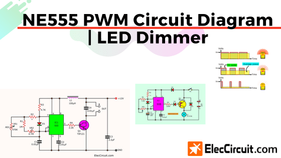
These DC Dimmer circuits have a lot of useful. For instance, the Lamps, Light bulbs, LED, DC motor controller, Coils, etc. And we can use up to 20 watts.
Basic DC Dimmer by Rheostat
A simple DC dimmer circuit that we see commonly, always use a variable resistor is adjuster voltage to load high-low as we need. However, we must use the high power variable resistors only, which always called “rheostat resistors”
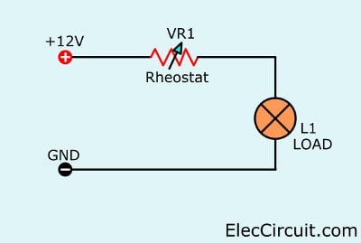
But the disadvantage of the circuit is so expensive and some power consumption loss in heat form. So, this way is so low performance.
Then, we found the best way that cheaper and high performance. It is PWM Controller as above. To briefly provide an output voltage with very high frequencies.
This dimmer with on/off time range of waveform to load, Not cause a loss of energy in the form of heat anymore.
What is more, See the saving battery.
Recommended: Recycle Free Li-ion battery from E-waste
Power Battery Saver Circuit
This is power battery saver circuit using an IC-555 timer. The lamp is controlled with a PWM mode by adjusting of potentiometer VR1. Whereas the PNP power transistor drives a lamp.
Sometimes, if the light bulbs or lamps are too bright, their lifespan becomes shorter and wastes too much electricity. On the first thought, you may be able to use a variable resistor in sires to control the brightness. But it does not work. Because it uses high power.
However, there are a lot of ways to fix this problem. This is in another way you may like it. It can save the power of a battery. The brightness of the light bulb is equal to the amount of power supplied to the battery.
Power saver principle
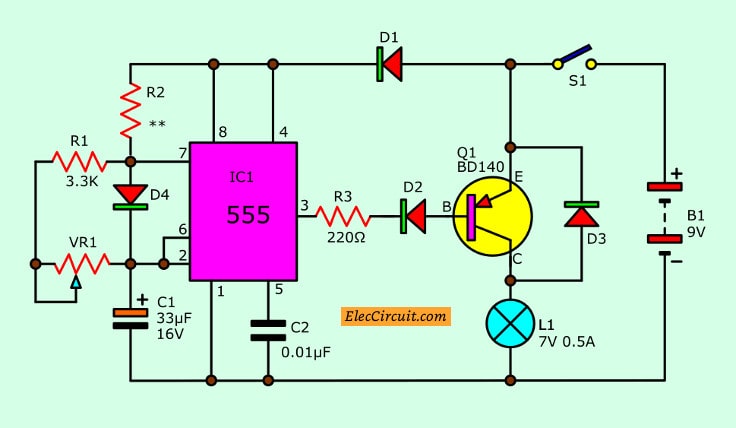
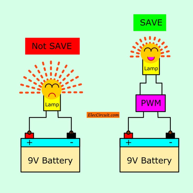
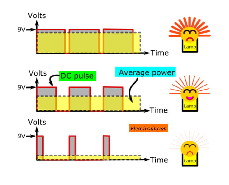
Usually, we will feed a normal voltage to the lamp. But a high power loss too much. Therefore, we need to fix the problem by adding PWM circuit control.
It will change a DC voltage, 9V. To become the DC pulse. Then, adjust a width of the DC pulse. To control the power to the lamp. Look at Figure below, you will clear better.
Recommended: How does NE555 timer circuit works
In this circuit, we use the NE555 timer IC as an astable multivibrator in the PWM circuit.
Which it will generate a frequency, DC Pulse to output. You can adjust the duty cycle or pulse wide by VR1.
The diode D1 to D3 is used to protect an incorrect power supply connection.
Learn more: Great electronic supplies stores lists for you
Parts you will need
IC1: NE555 Timer IC
D1,D2,D4: 1N4148, 75V 150mA Diodes
D3: 1N4007, 1000V 1A Diode
1/4W Resistors tolerance: 5%
R1: 3.3K
R2: 15K
R3: 220 ohms
C1: 33uF 16V, Electrolytic capacitor
C2: 0.01uF 50V, Ceramic
Q1: BD140, 80V 1.5A PNP Transistor
VR1: 1M potentiometer
L1: 7.2V 550mA Lamp
B1: 9V battery
S1: on-off switch
Recommended: How does an SCR work
Make Gel cell battery charger circuit
Anyway, we come back to see a better circuit below.
NE555 PWM Circuit as DC Motor Controller
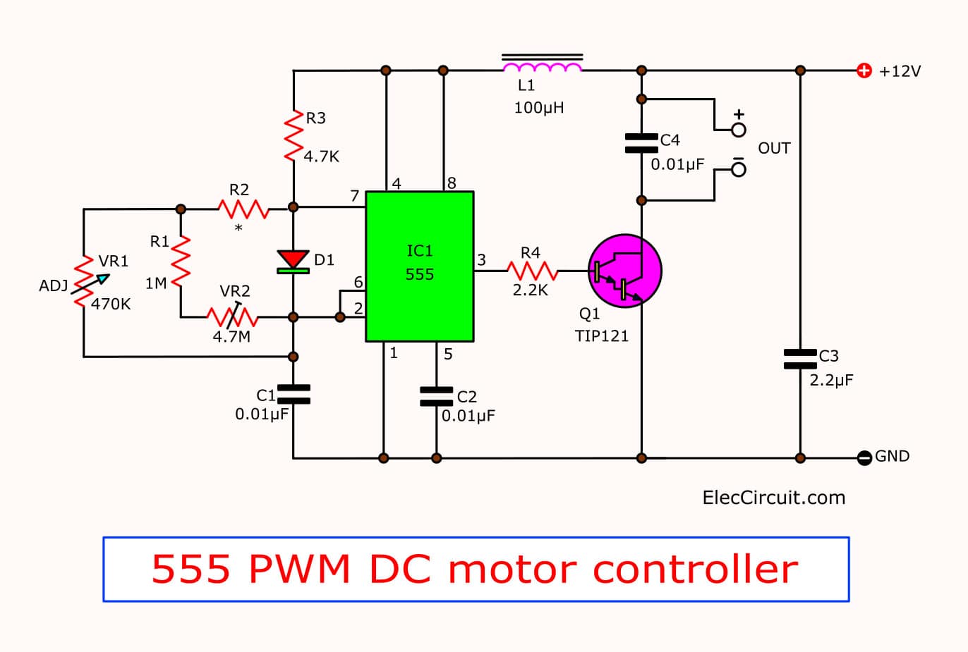
The practical application for these NE555 PWM circuits as shown in below. We will see that IC1-NE555 is a frequency generator to feed the transistor output. Which it serves as switch on-off voltage to a lamp in that frequency.
How it works
The output frequency of the circuit will depend on the value of R3, R2, VR2, and capacitor-C1. And, the time period on/off will depend on adjusting VR2.
From the value setting. We can adjust the time range:
On: Off rate Up to 100: 1.
Which we will provide to the load voltage of nearly 100%. That is the light bulb will be fully light. Or, if the DC motor will speed fastest, as well.
In the event that needs to the dimmer light. Also, we can adjust:
On: off range up to 1: 20
The output from pin 3 of IC1 will be fed through R4 to base Q1. It causes Q1 to turn on-off the voltage to a lamp as an input signal.
Then, see:
The working of transistors as above will cause the voltage drops across between emitter-collector between 0.7V to 1V.
And this is a loss of some power. But it very least when compared with the old circuit that uses the rheostat resistors.
What is more? Here is a function of other parts in this NE555 PWM circuit.
- The Diode-D1 acts as a booster of time range on-off wide up.
- The potentiometer-VR1 acts as the adjuster the output voltage lowest as you want.
- The capacitor-C3, C4 and L1 acts as reducing the noise signal from the circuit don’t interfere with other electrical circuits.
- For L1, we can make it up by using copper wire No. 20 SWG winding on ferrite cores about 50 times.
You may also like these:
- Simple 12V | 9V | 6V Motor DC Speed Control with PWM mode
- How to rotate DC motor in both directions
- 8 simple touch switch circuit projects
How to build
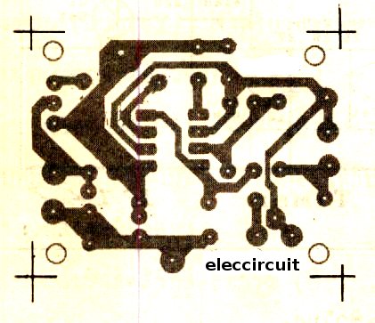
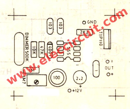
We can assemble the parts on the PCB as shown in Figures 3 See Positioning device based circuits correctly As Figure 4.
Keep the output transistor, It is tall and hot. So need to hold on a larger-size heat-sink.
The Actual-size,Single-sided PCB layout
The components-layout
When assembling the components as a done circuit, then adjust VR2 until the lamp a few glow up softly, next adjust until go out lowest light, and later adjust VR1 again to really low light.
The components list
IC1: NE555N or LM555, Timer IC
Q1: TIP120_transistors
D1: 1N4148_75V 150mA Diodes
0.25W, 5% Resistors
R1: 1M
R2: 10K
R3: 47K
R4: 2.2K
VR1: 4.7M (preset) Trimpot
VR2: 470K__Trimpot
C1, C2: 0.01uF 50V_Ceramic
C3, C4: 2.2uF 50V_NP
L1: 150 uH _inductor.
What is more? Let’s see DC spot Lighting Dimmer using 555.
Spot Lamp DC dimmer circuit using LM555
This is a simple low-voltage DC dimmer or PWM circuit. It can adjust the brightness of a maximum 12V 100W Power Spot Lamp from 5% to 95%.
This LM555 PWM circuit uses the LM555 as a free-running multivibrator to drive both power PNP transistor, to control the lamp with PWM mode. And, using a few other components. Which easily buy in most of the local markets.
Working of the circuit
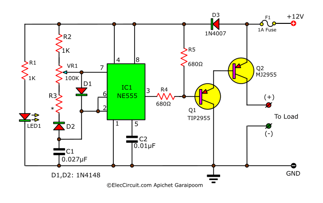
Spot Lamp DC dimmer circuit using LM555-TIP2955
In the circuit, we use IC-LM555 is free-running Astable Multivibrator mode. Which these components R2, R3, VR1, D1, D2, and C1 determine the frequency output pin 3.
Then, the circuit can change the duty Cycle by adjusting VR1-potentiometer and R3. They also control a brightness level as you want.
Next, the output oscillator will limit load current, the lamp ON and OFF at a rate duty cycle of the multivibrator.
After that, the current flows to the base of Q1-TIP2955 and Q2-MJ2955 to drive the load.
We should install Q1, Q2 with a suitable heat sink. When the circuit operates in full power. The Q2 is overheating. It may damage.
The D3-general silicon diode protects oscillator feedback. Which it can damage this circuit.
For a load of this circuit, you can use 10A 12V, power all lamps, or the strip lights LED, or high power LEDs.
The LED1 is power on display. The R1-series resistor to limit current in save value for LED1.
‘Keep reading: 555 Pulse Generator circuits’ »
Parts you will need
IC1: IC-555 Standard Timer Single
Q1: TIP2955 15 A, 60 V PNP Bipolar Power Transistor
Q2: MJ2955 15 A, 60 V PNP Bipolar Power Transistor
D1, D2: 1N4148 75V 150mA Diodes
D3: 1N4002 100V 1A Diodes
LED1: Red LED
R1: 560 ohms 0.25W Resistors
R2: 1K 0.25W Resistors
R3: 1K-100K 0.25W Resistors
R4, R5: 680 ohms 0.25W Resistors
VR1: 100K Potentiometer
C1: 0.027uF 50V Ceramic Capacitor
In addition, you can see other circuits. That also use for all power LAMP.
Keep reading:
- 12V-24 PWM motor controller
- SCR DC motor speed control circuit using IC-CMOS
- AC dimmer for LED Bulbs using IC-555 & TRIAC
GET UPDATE VIA EMAIL
I always try to make Electronics Learning Easy.
Related Posts

I love electronics. I have been learning about them through creating simple electronic circuits or small projects. And now I am also having my children do the same. Nevertheless, I hope you found the experiences we shared on this site useful and fulfilling.



#Spot Lamp DC dimmer circuit using LM555-TIP2955
A limiting resistor(>47Ω) in the collector of T1 must be employed. Otherwise, soon Q1 and probably Q2 will be history.
Hi
That Is a Vary Good Circuit.Thankyou
Hi siavash.
Thanks for your feedback.
Realy you are fantastic website that i see to now
Hiiiiiiiiiiii
mer30!!!!!!
thank you.
your web are very good.
Hi,siavash
Thanks for your feedback.
Hi,م.مصطفى المصرى
Thanks for your feedback.
Hi,abbas
Thanks for your feedback.
Hey I appliciated much the diagrams helps me much can I have more for how to make free power using altarnator and more about radiant power.
#Spot Lamp DC dimmer circuit using LM555-TIP2955
pls. how can i order parts
I need variable Capacitor 1-100 µf or executive the enclosed circuit
I wonder, the circuit should handle 100W load (9A) and the V+ is connected with an 1A fuse. How come??
#Spot Lamp DC dimmer circuit using LM555-TIP2955
Hello, Alexander Sergeyev
Yes, It may be wrong. You should the fuse rating follow load current.
hi, pls write ur name “Aleksander” rather than… . spasiba