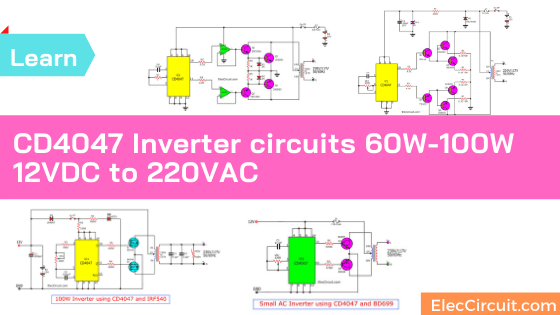
There are four CD4047 inverter circuits that can convert 12V to 220VAC 50HZ, we use IC-4047 for oscillators and transistors drive the transformers to output. We have 4 circuits you can build easily with PCB.
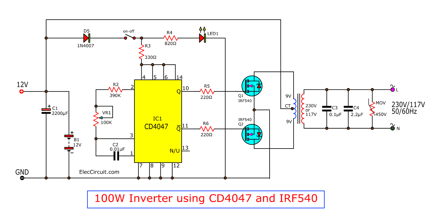
100 watts Inverter using IC-4047, IRF540
This is the inverter 100W circuit, use IC 4047 alike inverter 100W transistor I use MOSFET IRF540 instead Transistor 2N3055.
It good Idae, power output 100W from transformer 2-3A.
Read detail more in circuit.
How to use CD4047 Monostable Astable Multivibrator IC
How it works
The 12V battery comes into the circuit. The IC1 will work as astable multivibrator circuit. Makes it products the square wave frequency, 50Hz out of both pin 10 and pin 11.
Then, the bias gate of both MOSFETs(IRF540) It works alternately the same style as this circuit.
Try 555 and MOSFET inverter circuit
We use CD4047 because the output is 50% duty cycle. It is better than 555 timer IC.
Learn 555 timer works as oscillator
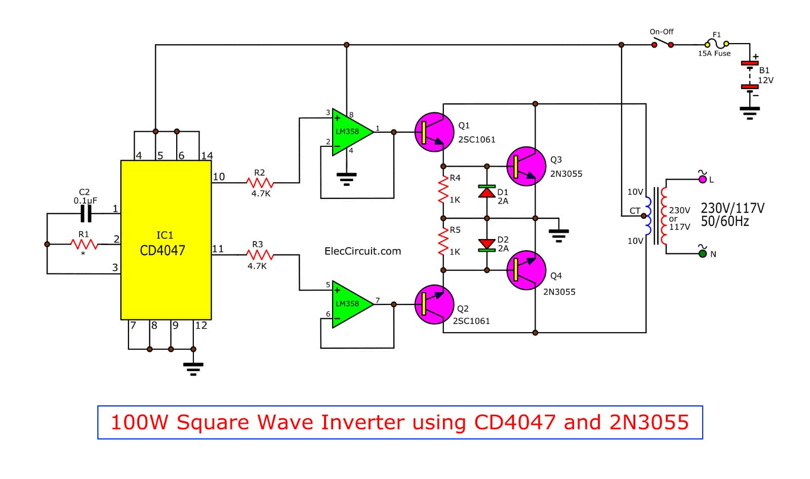
Square wave Inverter using CD4047,LM358,2SC1061,2N3055
This is AC Inverter. Input 12VDC from car battery to output 220V AC 50Hz or 60Hz at Square wave signal.
The main part is CD4047 (or IC 4047 Series) and IC-LM358 and Transistor 2SC1061 and 2N3055.
The transformer is 10V-CT-10V, Primary : 220V Secondary.
and current 3A up for power output than 100W.
Note:
C1 = 0.1uf metalized-film capacitor, 5% tolerance.
R1 = 47K for 50Hz output, 39K for 60Hz output.
100W Inverter by IC-4047,2N3055
This is 100W Power Inverter that input voltage is 12V (CAR battery)
to output volt 220V AC 50HZ. It is easy circuit because less component to use.
It is used IC CD4047 Square wave Oscillator 50HZ and
Power Transistor 2N3055 x 2 For driver a transformer 220V AC to OUTPUT Power 100W min.
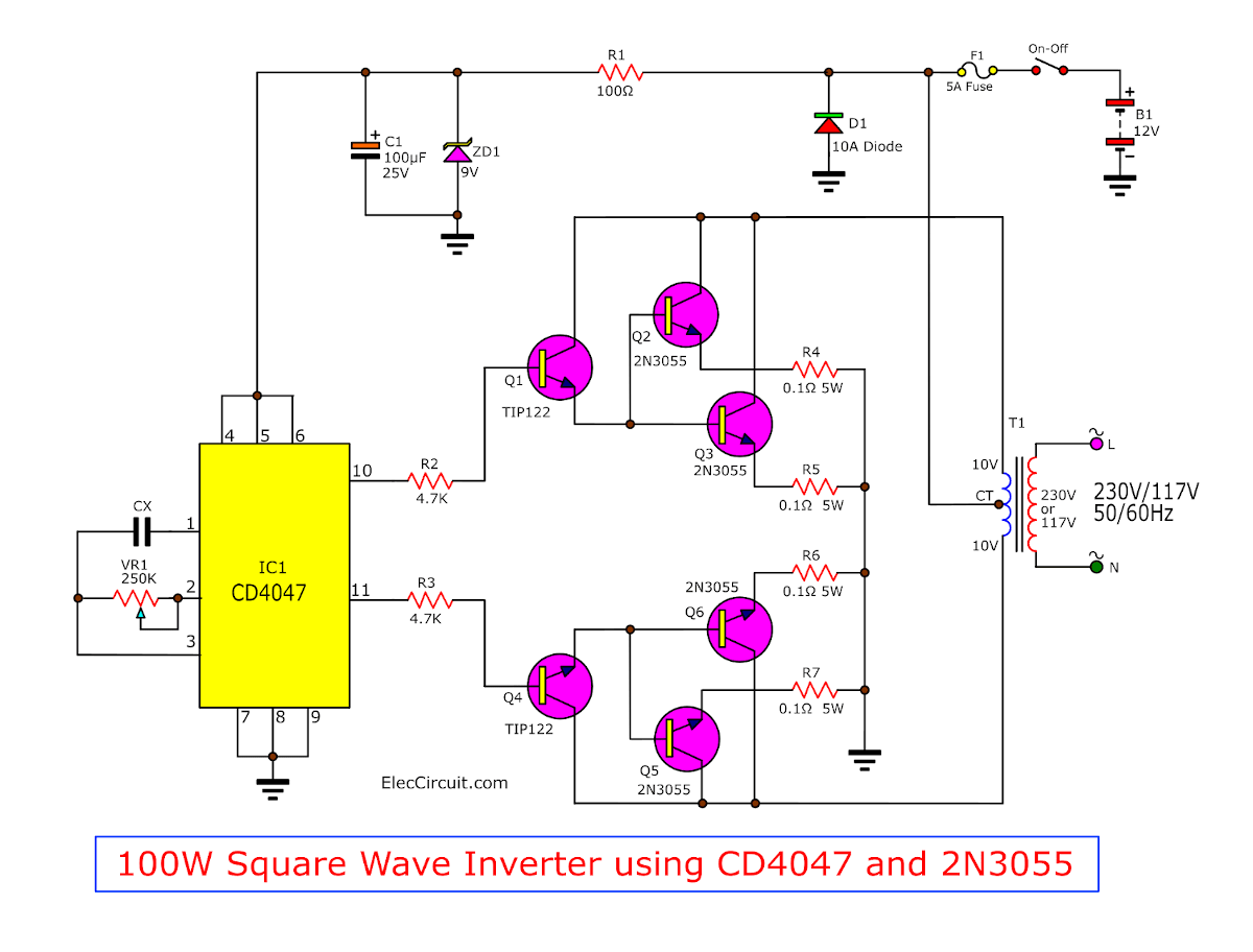
100 watts Inverter circuit diagram using CD4047 + 2N3055
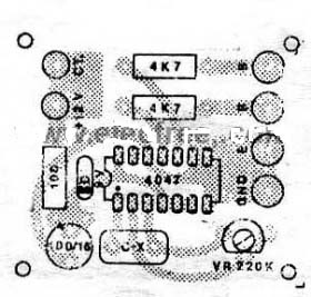
PCB layout of 100 watts Inverter circuit using IC 4047 + 2N3055
Source: 97 Electron Circuits
The components lists
IC1: CD4047
VR1: 220K, potentiometer
Cx: 0.01uF-0.022uF Ceramic capacitors
ZD1: 9V, 0.5W Zener diode
60 watts DC to AC converters circuit using IC-4047
This is a small AC inverter. There are very small amounts. For the experimental study. Because low power of around less than a 60 watt only. However, you still can get a good basic circuit course.
This circuit we use an IC-4047 as astable/monostable multivibrator that low power is main of circuit.
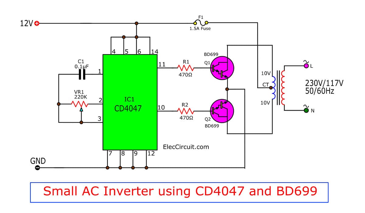
In the operation of circuit. To change the 12 volts direct current into AC electricity of 245 volts. Based on circuit in Figure 1 this. IC1 is connected to the astable multivibrator.
There is a Square wave signal appear at output pin + Q and-Q on Symmetric form. Then is amplified by dual Darlington transistors T1(BD699) and T2(BD699), and after then is send to Primary winding of the transformer low voltage (2x10v 60 VA)
The output of 245 volts at the secondary winding of the transformer with a frequency between 50 – 400 Hz, depending on the P1.
The transformer is used in small size input 9 – 10 volts to 220 – 250 volts at a current of 1 Ampere.
LET’s build the DC to AC converter circuit.
12V DC to 220V AC 50HZ about 60 watts output.
Using CD4047 and MOSFET
GET UPDATE VIA EMAIL
I always try to make Electronics Learning Easy.
Related Posts

I love electronics. I have been learning about them through creating simple electronic circuits or small projects. And now I am also having my children do the same. Nevertheless, I hope you found the experiences we shared on this site useful and fulfilling.

Pls how to build inverter 2.5kv, it’s project i need step to step explaination
Pls how to build inverter 2.5kv, it’s project i need step to step explaination. This my mail ( [email protected] ) thanks
thanks alot admin… but plz my problem iz how to wind a transformer manually till it works just by instantly connecting it to 12dc supply. I’ve tried to wind it myself but its not producing a continuous ac power. am saying this coz there’s a man who have been building his and it works well even before connecting the transformer to the circuit!
best greetings
dear Sir
it’s gives me much pleasure to write you this Modest words , Sir , I’m looking forward to make cheap converter of 12 VDC into 230 VAC 2000 Watts please give me simple schema to help me for that
your sincerely
Mr Aziz El kabboury *
researcher*
address key *
Collge Ahmed El hansali
at bouhmed rabia*
Beni Mellal *
zip 23030 BM*
Morocco
Plz Sent me a simple project in my mail id
Please I need a circuit diagram of 1500w of inverter that dc is 12 0 12 and 24 0 24 that operate in digital
Have made many of these inverters for friends using bipolars or mos. For transformer, I used
a high wattage 12 volts center tapped. This is readily available at electronic supply store.
this 100watt inverter with mosfet is not working. mosfet give to me 2v which canot be step up????
and at the gate of mosfet there are 12v volt then why mosfet not gave me 9v????
plz answer me sir…………
i want to submit my project tommorow
i need a circuit for the power supply assignment with input of 220v AC nd output of DC
Really no matter if someone doesn’t understand after that its up to other
people that they will assist, so here it occurs.
Please i need step to step explanation on how to make a simple inverter of jst 100vdc.thanks
please give ic 4047cd,irf540 functions,working,circuit diagram
please send m d working of 100 waatts , ic 4047 with mosfet irf540
plz rply by mail [email protected]
i want pcb layout sir, plz help me ……..
can we increase the output power by connecting mosfets in parallel ,do think it really works effectively,i mean does it increase the output power more than 100w
Please send me the working of this inverter..
hi vasudev..,
You can increase the output by connecting 4 mosfet s in paralal. You’ll get 250w-300w power. (Transformer must be rated to 5A)
sir plz heip me.i understand circuit.but i cant do drawing see and make.so plz heip me how i understand. my email id is “[email protected]” plz help me.
sir I want to specification of transformer to design capacitor filter after output of transformer . please give me inductance value of primary and secondary
I need a schematic circuit for an inverter that inverts 24Vdc to 220Vac with 200W power
Hi,
Please look for : https://www.eleccircuit.com/how-to-build-the-200-watts-home-inverter-projects/ or Read detail again.
Is there any replacement for BD249? Thanks.
i Want inverter manufacturing Procedere and main components of its.
I need a schematic circuit for an conductivity analyzer in pspice.please help me
i want inverter manufacturing Procedere and main components of its,
and the verious functioning of component (thier role in the circuit).
Please what is the cost of running a solar+inverter connection for a two rooms apartment and will appreciate a circuit diagram.
mini car inverter circuit of 60watts using CD4047 ka complit kit chahiye speed post se mil sakta hai kya ?
How come a 9-0-9 1.5A transformer serves 100Watt? Simple physics suggests its good enough for 14.5 watt max. Stop ruining the internet by publishing these shits all over the website. NONE of your circuits are based on facts, most of them are untested and not working. HATE HATE and HATE for you!
i find that stuff interesting** ►► 2. 100W Square wave Inverter by CD4047, LM358 ◄◄
→ 4k7 resistors noise filter and smooth OpAmp inputs
→ low bandwith , low slew rate Op Amps !! quite likely !! provide non-overlapping drive for power switches
→ no unnecessary components — nice , simple , clear
(although as the previous comment states – you need a good transformer and or cooling – to run it more than apx. 2 seconds on 100W output) + as i’m not too familiar with such designs — if we have a secondary open then the power likely regenerates proportionally at not active one at primary side . . . and might enter the Op Amp output + inverting input through NP collector-base junction of 2SC1061 . . .
→ . . . otherwise anything that’s already there** looks nice — i like that circuit (although i wouldn’t power it up like that)
is it posssible to invert 1.5 volts into 220 volts
I have a problem, sir.
My quarry is, how to control inverter’s output voltage? (100watt 250volt ,with ic CD4047)
sir,
in what ic can use when it run the washing machine .
Hello, saif
Thanks for your question.
These circuits cannot power to the washing machine out of 300watts up.
Because its the output is not more than 100watts.
You sure it work?
Hello Desinger,
Thanks for your question.
Please look at https://www.eleccircuit.com/dc-to-ac-converter-circuit/
It works for sure! with PCB layout.
These circuits above are also working. But I cannot tell you it works in 100%.
I like the CD4047. It is easy. You can use it in many ways.
what are the components given in the circuit
o cd4047 pode trabalhar em onda senoidal?
Hi boanerges pereira dab silva,
No, Use ICL8038 better. Keep Reading: https://www.eleccircuit.com/mini-function-generator-circuit-using-icl8038/
Please after designing my inverter with 4047, one of the output of Q goes high contineusly.
Please what can I do to bring both output pin 10 and 11 at same level.
Send me reply and thanks in anticipation.
Dear Sir
Please kindly help me with the PRINCIPLE OF OPERATION OF THE INVERTER 100W 12VDC TO 230VAC BY 1C 4047-IRF540
Hello Lungile Samantha Ngwane,
Thanks for visiting. This circuit is interesting.