Imagine you have a small party. Turn on great music. Friends really appreciate your audio system. These 100W transistor power amplifier circuits may make it true.
Although these are Classical amplifier circuits for over 40 years ago.
But if people love music. They are not outdated.
We use only all-transistor, MJ15003 and MJ15004 are the main in circuits. And the power supply +38V 0 -38V 3A. Because it is a style of OCL amplifier.
Specifications
- Power output : 105watts at 4 ohm load, 88watt at 8 ohms load
- Input sensitivity : 0.5V
- Frequency response : 10-10kHZ +/- 1dB
- THD: 0.07% at 50 watt , 0.1% at 100 watt.
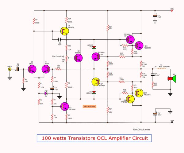
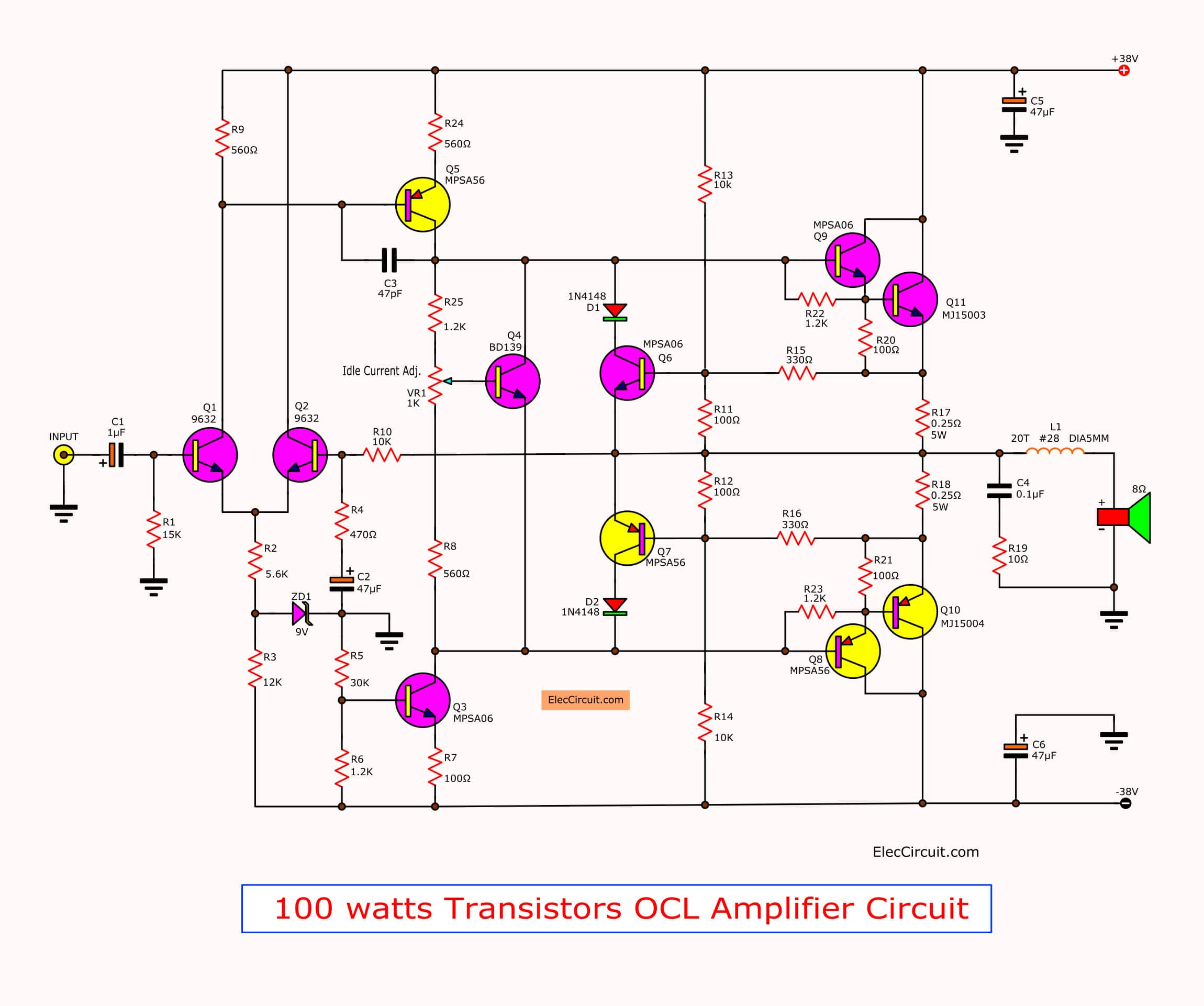
A circuit of cheap 100 watts transistor power amplifier project
How it works
This 100W OCL power amplifier is excellent sound quality. In the circuit uses all direct coupling connection together. To cut-off frequency low-loss problems the super bass.
Note:
Because the details in the article are too less for beginners And it needs some skill like good quality soldering. However, if you accept any damage that happened later. Yes, you can. Let’s get started.
It is so hard that explain you understand how it works in simple ways.
Here is step its process.
- First, enter a signal from the tone controls to the input. C1 passes the audio signal to the base of Q1.
- Q1 and Q2 connect together as the differential amplifier. To increase low audio with reducing noise input.
- Then, the signal from the collector lead of Q1 flows to Q5. It is a pre-driver amplifier circuit.
- The transistor Q4 sets a level bias or act as to control Idle current in this circuit. Which we can adjust level idle current By adjusting the VR1.
- The transistor Q3 acts as a boost trapping.
- The output signal of Q5 comes in the base of Q8 and Q9. Which they act as the driver circuit. For the signal output to drive the output transistors Q10, Q11.
- See both output transistors Q10 and Q11. We use MJ15003 and MJ15004. This couple can use up to 200W. So no problem in durability.
If you want to save.
Some use a pair of these output transistors to connect in parallel instead.
- Two 2N3055 instead of MJ15003.
- Two MJ2955 instead of MJ15004.
- Two MJ802 instead of MJ15003.
- Two MJ4502 instead of MJ15004.
Short datasheet
- 2N3055: NPN, 60V(Vce), 15A(Ic), hFE 20-70
- MJ2955: PNP, 60V(Vce), 15A(Ic), hFE 20-70
- MJ802: NPN, 90V(Vce), 30A(Ic) 200W, hFE min 25
- MJ4502: PNP, 90V(Vce), 30A(Ic) 200W, hFE min 25
100W amplifier Power supply
This circuit requires enough energy source.
Look at below.
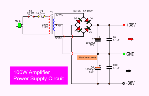
It is a 100W amplifier Dual 38V power supply circuit diagram.
It can power output +38V Gnd and -38V at more than 3A current.
How to build
You can assemble and set this project as step as follows:
Parts lists
Get all parts first:
Q1, Q2: MPS9632
Q3, Q6, Q9: MPSA06
Q4: BD139
Q5, Q7, Q8: MPSA56
Q10: MJ15004
Q11: MJ15003
0.5W Resistors, 1% tolerance
R1: 15K
R2: 5.6K
R3: 12K
R4: 470 ohms
R5: 30K
R6, R22, R23, R25: 1.2K
R7, R11, R12, R20, R21: 100 ohms
R8, R9: 560 ohms
R10, R13, R14: 10K
R15, R16: 330 ohms
R17, R18 0.25W 5W
R19: 10 ohms 1W
C1: 1uF 50V Electrolytic
C2: 47uF 16V Electrolytic
C3: 47pF 50V Ceramic
C4: 0.1uF 63V MKT Capacitor
L1 coil
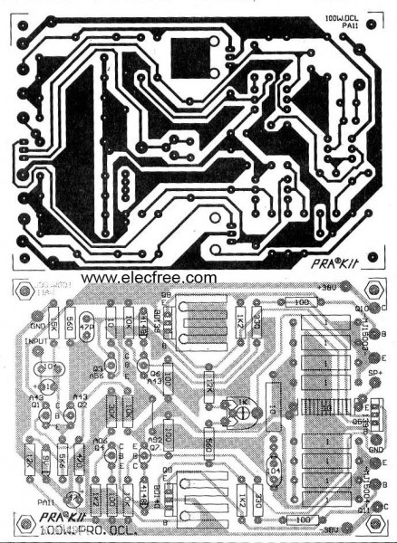
Then, assemble all part on the PCB layout as Figure below.
PCB of The cheap 100 watt transistor power amplifier project
Setting and Testing
- Check the assembly of all equipment to correct the circuit without the output transistors.
- Use a voltmeter measure the voltage at the speaker terminals but without a speaker.
- At the end of this process was completed and ready to operate immediately.
- Put the power supply to the circuit.
- Then to measure the voltage is 0V or not higher than 0.25V. If not same this, it means that the circuit failure, need to check first.
- Then a short input circuit. And measure the current of output power transistors with an ammeter. And, adjust VR1 until reading about the current 20-40 mA.
- Should install transistor Q4 with the output power transistor heatsink. To help control the bias current output relative to the temperature change of the output transistor.
- The power supply circuit is got by the power of transformer T1, which provides voltage to the coil in the secondary coil is 27-0-27 volts, 5A.
- The Diodes Bridge rectifier should be not lower than 5 Amp 100V, The filter capacitor C7, C8 we used a 1,000uF 50V, the voltage at the capacitor after through the filter will can about 38V.
Caution! This project needs to use the speaker protection circuit. Otherwise, your speaker may be damaged.
Other 100W transistor OCL power amplifier
Keep reading: ‘2CH 100W stereo audio amplifier’ »
GET UPDATE VIA EMAIL
I always try to make Electronics Learning Easy.
Related Posts

I love electronics. I have been learning about them through creating simple electronic circuits or small projects. And now I am also having my children do the same. Nevertheless, I hope you found the experiences we shared on this site useful and fulfilling.


Hi!
Can anybody send me pcb project of this amp in better quality?
THX!
hi I assemble this circuit it working good but it get too much of heat even without load the output transistors get too hot i use 2sc3855 &2sa1492
Substitute for mps9632 transistor. This same transistor not available in our place.
Hi,Elekros90
Thanks for feedback. Now I cannot show you good better than this image PCB.
I am sorry for my error.
Hope you come back to see again.
Hi,kanagaraj
Thanks your feedback. I am happy that you build this project in long time ago (than 20 years) I use this dual transistor so old circuit.
Thanks for sharing.
I want to amplify 10mW (10V over 1k ohm output impedance) to about 100W over the frequency range 10kHhz – 500kHz. Linearity is not at all critical since the signal is pure sine wave or possibly square wave. Would you for a fee design a suitable circuit for this? It would be an advantage but not neccessary if the output could be varied.
Hi,Jan Kristensson.
Thanks for your feedback.
This circuit may proper for your job.
https://www.eleccircuit.com/100-watt-dc-servo-amplifier-by-power-mosfet/
what transistor should i place in Q1 and Q2
I like this circuit, very simple and straight forward.
Hello!!! Can this amp be connected in bridge mode?
I am extremely interested in building my own 100W RMS power amp and power supply.
The one I’d love to do as a project Is the one shown in the schematic diagram. Please let me know the prices involved and how I can purchase it….thanks a ton
Neil.
I was Constructed a 30W+30W Cassette Deck very long ago, using N055 & P055 Transistor in Golden PCB. Recently all Transistors are burnt out but, I want to repair the Amplifier. I have lost the book. I did not find the Transistor or Circuit Diagram anywhere. Please give me the circuit diagram of the amplifier of N055-P055. And suggest me where can I find the Transistor or its substitute.
Thanks in advance.
Are you still interested in your no55/po55 amp ? I have a circuit diagram !
pls I want detail journal on the 100watt OCL power transistor audio amplifier with PCB thanks.
hi
i am new in to design and planning to assemble this amplifier. i have one question here is. what is the use of Q6 and Q7 transistor here. what is role of this two transistor.
regards,
suhas
Hi Suhas,
I am happy you love music to build the power amplifier.
Both transistors are protection for power transistors when overload.
Nowhere Q6 and Q7 transistors working principle illustrations by the Author. It is I presume short circuit of Speaker output terminals, as these transistors will stop supply to output transistors and thus protection against short circuit.
Is it ?
Hey, What dimensions are the PBC ?
Hello, could it be possible to put a link as to where the pcb’s can be purchased from? Thank you so much.
Hello Jacques Franken,
Sorry, I am not selling this PCB.
Quero diagrama esquemático amplificador Mark áudio pm4-800
Hello, Pedroseverinidossantos
Thank you for visiting.
I do not have that circuit. However, do you see here? https://www.eleccircuit.com/amplifier-circuit/
I am sorry that may help you.
Thanks
Hello Apichet Garaipoom, good day, i want to contribute financially, i see your paypal me link
But i don`t see your direct email address
Please get back to me about my financial contributions
Hello Arnold Palmer
I am very happy today. Thank you for seeing that My work is useful. Your support It is a great encouragement for me. I will keep working happily like this.
Please Donate through PayPal: [email protected]
Or
paypal.me/agaraipoom
Name: apichet garaipoom
Have a great day
Thanks a lot
Apichet
what type of transformer is used in your power supply
is it a toroidal or normal transformer