Here are LM3914/LM3915 VU meter circuit projects. They can display with 20 LEDs on stereo, or mono with 10 LEDs for all audio system.
Also, we can easily build and cheap. We will be happy when use them.
Do you believe it or not? I have seen VU meters for more than 40 years. Until now, it is still very popular. Why is that? Read below.

I have made a lot of amplifiers. Because I like to listen to music. Also, I like the VU Meter circuits, too. They show the power level of the audio. It is so beautiful.
Many friends may prefer them same me. When you go to an electronics store to buy a VU meter KIT. In pattern, assemble the various parts by their own and ready usage.
Why should build the LM3914 VU Meter circuit?
Most freiends choose the LM3914 VU meter circuit. Because it is convenient, easy to modify in many form.
Today I assemble these circuits using this IC. Sometimes you are looking for ideas on this
For example:
The flashing lights by the music, to decorate the Christmas tree, exotic, and unique.
This project is very easy. Because of use alone IC only and a few external components.
The display system can drive directly LED up to 10 LEDs and display as light running is DOT or BAR as you want. See the circuit below.
The working principle
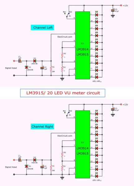
Electronic VU meter circuit diagram using LM3914 / LM3915
The main of this circuit is LM3914N or LM3915. Which the external circuit is the same.
Difference of LM3914 & LM3915
- LM3914N will display an amplitude of a signal in Linear form.
- LM3915N will display the signal in Logarithm form.
- LM3916N: Update The outputs can drive, LCDs, vacuum fluorescents, and incandescent bulbs, as well as LEDs of any color
Normally if using the amplitude of the sound signal. We should use the LM3915N.
Thanks ODX: we can use LM3916 for this circuit, too.
See in the circuit above again.
The input signal from the power amplifier will be entered through to Voltage Doubler circuit consists of C1, C2, D1, D2.
They will convert sound signal voltage to DC voltage and have amplitude are 2 times of the input signal.
Then, insert a single to input pin 5 of IC1.
And next IC will compare the signal amplitude, to drive LEDs display follows the amplitude of input signal as above.
The Mode selection in working of the circuit. To display in DOT or BAR form. We can select switch S1 to control pin 9 of IC1.
Which if release the switch S1, it will display the bar form.
But connected pin 9 through switch S1 to a positive voltage of the circuit. It will display in the DOT form immediately.
The power supply
This circuit requires 9V to 12V power supply. we have 2 options to do easily.
Build this project
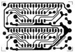
First of all, make the PCB layout in stereo or mono as you want.

Then see Mono form here.

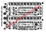
Secondly, Soldering all components into the PCB, as you see in (stereo form).

and Mono form.

Caution:
Polarity of LED must be placed correctly. If you reverse the polarity, the LED does not light.
The Shopping lists
IC1: LM3914N, LM3915N, LM3916 Dot/Bar Display Driver
D1, D2: 1N4148, 75V 150mA Diodes
0.25W Resistors, tolerance: 5%
R1: 10K
R2: 2K
R3: 3.9K
Electrolytic Capacitors
C1, C2: 1uF 50V
C3: 47uF 16V
LED1-LED10, LED 2x5mm LEDs.
Note:
1. If you need to print the PCB layout please check 200 dpi per inch on the image scale.
2. In PCB layout does not have C3. But we can add it power supply terminal. Or if you use a regulator. You may not use it.
3. If you not like this circuit please look at:
Transistor VU meter
GET UPDATE VIA EMAIL
I always try to make Electronics Learning Easy.
Related Posts

I love electronics. I have been learning about them through creating simple electronic circuits or small projects. And now I am also having my children do the same. Nevertheless, I hope you found the experiences we shared on this site useful and fulfilling.


I have a circut for the LM3915 that says its expandable. Using the mode (pin9) And If in a mono setting can I daisy chain 3 of the 10 LED sections to make a long 30 LED display? (60 if you consider stereo) Or am I misunderstanding the text. Is it only expandable in multiple rows of 10 LEDs maximum.
I need a precision LED VU stereo = 60 LED (2×30)
To save money, Ive purchased all the necessary colod LEDs but still concern that the 6x LM6315 can do it.
See LM3915 and LM3914 VU meter projects :
https://www.eleccircuit.com/electronic-vu-meter-by-lm3914-and-lm3915/
Dear Admin, how can I adjust this kind of 10-level VU-meter for controlling a LED strips? I want to make an LED VU-meter wall. LED strips works on 12Vdc constant voltage and they already have a SMD resistors for current limiting. So I need the output signal on 12Vdc level. I have some commercial amplifiers for amplification (the RGB amplifiers with common anode) so the amplification is not a problem. Hope for an fast reply.
Thanks in advance!
Can i use the lm3916? Arent they the 3 IC that do the same?
Josh I am currently using an LM 3916 in this circuit with no problems
Hello ODX
Thanks a lot for your information. You are great.
Hi ODX,
many thnaks for your great works.
I’d like to know somethings more about the following vu meter “https://www.youtube.com/watch?v=Kt4xdCHKK5I”:
1) in order to realize it did you use the mono configuration (with led in parallel)(Figure 3) or the stereo layout (Figure 2) or “Level indicator with 10 LED” that you post on https://www.pira.cz/enbar.htm?
if you use the mono configuration or “Level indicator with 10 LED” could you let me know how can I wire 20 leds instead of 10 led as in figure 3?
On your youtube video you say “20 LED’s (9 colors) wired in parallel for the plexiglass sheets and the arrays also wired in parallel”
It would be great if you could you post some photo of front and rear with more detail of the PCB that you have made.
Excuse me! i just wonder that aren’t the 12V burn out the LED as LED needs only 2V each.
Any comment is appreciated 🙂
Hi. Mario. Thx for the interest. If you can post an email here I can send you a few more pix of the build and hopefully explain a bit more.
Hi ODX,
thanks for your kind e fast reply.
My email is [email protected]
thanks againg 🙂
Hi Daravuth. Some LEDs use around 2 V and some other colors use 3+ V. Yes the LED will burn when connected directly to a 12 DC source. I am currently running 6 V. on my tower BUT have run it with 12 V without any problems. I have no resistors attached to the LEDs to step down the voltage so I’m guessing there is some internal resistance on the 3914,5,6 that compensates for this.
I would like a meter with a 0-2volts input signal reading. What resistor (s) controls the step levels between the led’s and how do I determine the values of the resistor? Can I use either the 3914 or 3915?
thanks man, this works great with subwoofer’s output signal.
Hey man! I just wanna ask if this project is capable of running on a 5v supply or simply usb powered vu meter?. any components needed to be replaced or none? thanks man! 😀
I want to share my experience. LM3915 work well on 5volt dc. you can use 7805 make this voltage from 12volt dc. If you want to use more led ex two led or 4 led in pararel,you can use PNP transistor,wich the BASIS is conected to the pin IC.. don’t forget to give resistor from Basis to the pin ic. 1 k ohm is fine. Emitor of transistor can be conected on 12volt dc. but the LM3915 conected to output 7805, of course 5 volt in order to make the IC LM3915 not burning or overheat. the 7805 should be conected with the heatsink. hope helpfull
Sir I want to make 40 led vu meter using 4×3915. Can any one tell me that how to connect multiple ic 3915/3916. Please help. Thanks in advance!
this web page is useless and whoever wrote it has no gramical skills
you miss spelled grammatical
Hello bob the fish,
Thank you very much for your time. To give my opinion.
Yes, my English is pretty bad. But I will continue to develop it. I promise that if you revisit my website again. You can see that I improve.
Thanks again.
Apichet
Well BOB.. It looks like some people have no spelling skills either….”gramical”??? Now there’s a new one to think about.
i tried 1st circuit which shown in this page. in bar mode the 2nd led glowing continuesly. what i.l do for solve this problem?
Is it possible to buy the PCB from anywhere? I live in the UK.
Hi guys
i hve dne ths project .as per the above circuit and same components .its cooll
…………..
Hi there
Can you tell me – pin #9 connected w/ something or not? I’ve checked datasheet and it says that pin # 9 should be connected to pin #3 through the switch
ELatestark…Pin # 9 does not need to be connected to anything BUT if you wish to display DOT mode shorting pins 3 and 9 (using a switch) will allow you to do so. If pin 9 is not connected your display will show BAR mode. Wiring in the switch allows you to choose 2 different display modes.
Hope this helps.
And also, on the scheme C1’s polarity is positive on IN, but on PCB negative of C1 is on INput
Hey,
So I used a similar build like you have, but I have a small problem. Basically, if my input signal strength is about 80%, it works fine. Less, looks bad, more, all LEDs light up and looks even worse. So I’m thinking of using an amplifier, but if I increase the volume, and the amplifier amps it up, it’s going to be bad. So how about wiring a digital potentiometer into the circuit? Would that possibly solve all my problems? Or both amp and pot. I’m not really sure. You have any ideas? This way, my led tower is hugely dependant on me keeping up my pc volume high, and that’s a bad idea. Hit me up if you can here, or [email protected]
Thanks!
This is awesome !, how many leds can i connect in series/parralel ? i plan to make a circuit like this https://www.youtube.com/watch?v=Jyrpx9rEGMI using your driver.
Stereo PCB circuit didn’t work…
https://www.youtube.com/watch?v=XqxRNfGCZjY
Hi ,binh
Thanks for your feedback.
Good job!
hello, cool project ! but where is the place C3 on board ? no 47uf cap on board