Let’s create a 9V regulated power supply circuit to replace a 9-volt battery. These circuits can deliver 10 times more current than a battery and saving us time and money to replace it when it died.
They are also safer than a normal switching power supply. To find out more read below.
If our circuit requires a 9V power supply usually we will use a 9V battery, it is both easy and convenient. But if there are many circuits that require these same 9V batteries. It can be expensive and unnecessary to buy more. Therefore, we pick this 9V regulated power supply circuit instead of those batteries.
Simple circuits
We will bring up these 6 example circuits, by focusing on inexpensiveness, few components used, and high effectiveness.
There are both transistor circuits and an IC version, so my daughter to learn about this IC circuit. It has been working well during our testing session.
Noted that if we compare complexity between IC and transistors, surely IC will be more complex. Because the IC consists of many transistors. For normal usage, it is easier and more efficient to use one IC instead of transistors.
Since there are many circuits in this list, we will be listing these circuits from simple to hard in terms of complexity.
Most straightforward 9V power supply circuit
When choosing the circuit, I always use the concept of economical and suitable first. Comparable to “do not use a sledgehammer to crack a nut”.
Sometimes our load only required a low current or an uncomplicate load such as light bulbs, a small DC motor, etc. We can use common power supplies, so there is no point in using a larger circuit. Also, the smaller is the cheaper.
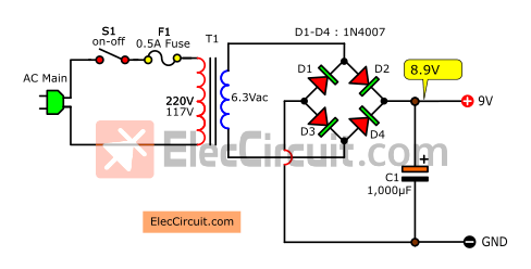
This circuit is an unregulated power supply circuit. Which is used extensively in an AC adapter in the old days. It has quite a weight because of the transformer inside.
The principle of this circuit is very simple by only having 3 main components.
The transformer—Converts a high voltage AC-main to low ACV at about 6.3V.
Bridge rectifier—It will rectify the voltage from AC (Alternating Current) to DC (Direct Current).
Filter capacitor—Smooth up the pulsating voltage from a rectifier to a steady direct current (DC).
Adding more capacitors in parallel with C1 for more capacitance. To get a smoother DC voltage and low ripple voltage.
Now the output voltage is DC and the voltage rise up to 8.9V.
From this simple formula of DCV = ACV × 1.414
= 6.3V × 1.414
= 8.9082V
This circuit can output a current of 0.5A limited by a 0.5A transformer we currently using. But if you want more output current, you need to change your transformer to the higher current one to match your desired current. As well as the diode current has to be changed to that of the transformer’s current, you also have to increase the capacitance of the capacitor.
For example, if we need 1A output current. We have to use a 1A transformer, 1N4007 Diode made for 1A current and a 2,200uF C1 capacitor.
How to choose components, Learn HERE: Unregulated Power Supply
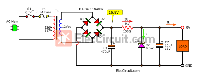
Simplest 9V DC regulator circuit using Zener diode
If your load requires a little current but a steady voltage such as a transistor pre-amplifier circuit, battery indicator circuit, etc.
In this case, using the Zerner regulator is a better choice. It can deriver output current of about 30mA to 50mA.
This circuit is quite simple indeed.
How it works and choosing components
I tend to avoid complicated calculations. Because we just want to use it for real hobby-level only.
The output voltage is fixed at 9V according to the 9V Zener diode voltage. The Zener Diode will keep the 9V constant voltage to load. The output current can be set with R1, we set it to about 50mA.
It receives the DC voltage from the unregulated power supply in the same way as the first circuit.
T1-transformer
The important thing is choosing a transformer. Normally, the secondary coil of a transformer will be 9V, 12V, 15V, 24V, etc. The proper voltage level is 12V for this circuit, it is also easy to find too.
And this circuit requires very little amount of current. Therefore, a 0.25A transformer is more than enough.
C1-Capacitor
According to my own experience the rough estimate of C1 that’s easy and works well is:
If the current of the transformer is 1A, we should use a 2,000uF capacitor. If using more capacitances, the effect is lesser until wasted in vain. But if fewer capacitances, there will be a higher level of ripple voltage.
Our transformer is 0.25A, thus we should use 500uF. But it can be hard to find. So, we used 470uF instead.
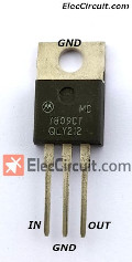
9V power supply circuit using 7809
Nowadays, ICs are very cheap compared to transistors. Probably because when something is popular, they will produce many of it. And there are also many brands that compete with each other.
Not so long ago, I had my daughter try a small digital oscilloscope, it works very well. It is suitable for small experiments. It only requires a constant 9V power supply (In the manual says so). So I have been using a 9V battery since, but it uses 98mA of current, therefore not suitable for small batteries. They can only supply 150mAh.
So, I decided to move to a cheap 9V AC adapter instead. The voltage was measured at 9.15V and stable.
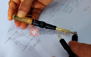
But when touch the metal parts of the probe or the circuit that is being measured, there is an electric shock. And when check with the Neon screwdriver.
There was a slight leakage, it is very dangerous. We should be replaced it with another power supply. This is a common problem with Switching Mode Power Supply (SMPS) if it is of poor quality.
There is also a high noise problem. It is not suitable for high-accuracy electronic circuits or related to high-sensitivity audio signals.
In the past, I used other linear regulated power supplies which have non of this problem. By using regulator ICs such as LM317, LM350, UA723, etc. Therefore, we will build a 9V regulated power supply using IC7809.
How it works
This circuit has higher efficiency than the other two before. The unregulated power supply part is the same as the circuits above, except for the max current, which has been increased to 1.5A.
We want to squeeze out as much performance as it should be.
First, we should set the best suitable input voltage and current level for the 7809.
In theory, 7809 can output a voltage at 9V and a current of 1.5A max.
But in practice, if we use 1.5A of current, the output voltage will drop to 7.5V or 80% of its output voltage in theory.
The 9V stable output voltage achieves at under 1A current only. However, this is enough for common usage.
I have tested it, it will run with total efficiency if an input voltage is more than 13V but not over 24V. If the voltage is higher than 20V, 7809 temperature will greatly increase until it became untouchable in the process.
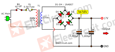
Look at the unregulated power supply circuit for 7809
When we use a 12V 1A transformer. It outputs about 17V DC voltage and a max current of about 1.5A.
Normally a 1A transformer should use a C1-2,200μF capacitor. But adding one more C2-1000μF capacitor, it will make the DC voltage even smoother.
When we intend to use this circuit to test various electronic circuits. We should add some components to increase the efficiency of this IC.
Next, look at the 7809 9V 1A power supply circuit.
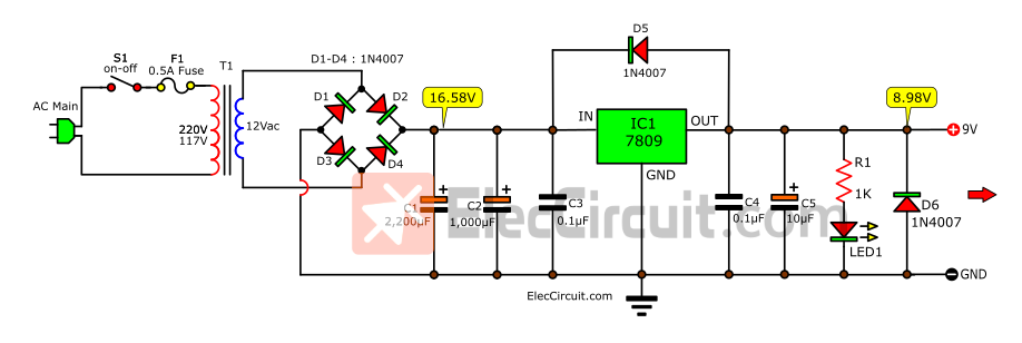
C3 and C4 capacitors To reduce the noise.
Under normal loads, their effect is barely visible. But when used with high sensitivity circuits such as preamplifier circuits, Digital circuits, and Op-amp IC circuits. If without these two capacitors, slight noise will occur immediately. It will definitely affect our circuits. So, we need to put C3 and C4 as a Spike remover.
C5 capacitors to increase the efficiency of the circuit.
When the load consumes a lot of power, the C5 help stabilizes the output current. We can opt for 10uF to 220uF. But we have found out that using only 10uF resulted in almost the same efficiency as 220uF. So, we use just a C5-10uF capacitor.
D5 and D6 diodes to protect 7809.
Although the 7809 has good protection including short circuit protection, overheat protection, and more. But in some cases, there is a high negative voltage flow back from the output. The IC has no protection against this voltage.
Some load circuits may have a capacitor, when discharged it will send out a high negative voltage. Which can flow back and destroy the 7809 immediately. So, we should put D5 and D6 Diode protection as same as 7805.
LED1 to indicate this circuit is normal.
When the output is normal at 9V, LED1 will glow. But if the output error such as a short circuit, lower voltage than 9V, etc. The LED1 is gone. The R1 resistor is a limiting current for LED1.
How to builds
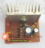
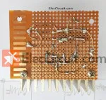
We assemble this circuit on the perforated board. It is quite fast to create the circuit but it might not easy for beginner. My daughter like soldering.
Here is Bottom of the perfboard diagram. We connect leads of components to create the circuit.
When we complete this circuit I tried to check with a neon lamp screwdriver to measure the AC high voltage again. It does not AC voltage leakage at all.
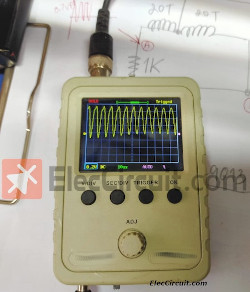
And when experimenting with a small digital oscilloscope, it works well. It can measure the frequency signal without any distortion.
- See many: 5V and 12V power supply circuits
Transistor version
Although the IC circuit from high efficiency. But the transistor circuit is very interesting to study. If you have the time and thirst to learn it. Please read below.
9V positive voltage regulator using Zener diode and transistor
If you are looking for 9V 1A regulator circuit. First, you will use IC-7809. It is easy and cheap. But now, we will come back to use the old circuit but still useful.
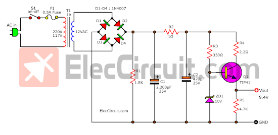
In the circuit above shows a simple series voltage regulator using a transistor and Zener diode.
Keep reading: Small Zener diode voltage regulator circuit with PCB
This circuit has a low pass filter. Which it is a special circuit that includes C1, R1, and C2. They help us to remove AC ripple. The voltage across C2 is a very stable voltage source.
The Zener diode-ZD1 provides the reference voltage. It has a value of 10V 0.5W.
ZD1 keeps the voltage constant across the base of Q1.
Q1 is a power transistor, gives the high current to load. The output at the collector of Q1 has a voltage across the load of 9V. Because of some voltage drops in BE of Q1.
R4 is a safety resistor for Q1. It acts like a fuse that protects Q1 when too many currents.
We can use the many NPN transistors like 2SC1061, 2SD313, TIP41, MJE3055, and more.
Learn: series circuit
9V Variable voltage (6 to 12V) DC Power supply
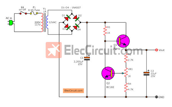
This is a simple DC regulated power supply circuit. The output voltage gives the fixed and variable voltage from 6V to 12V. We can set it is 9V with adjusting of potentiometer-VR1.
The max current is 1A. We should choose a power Transistor-Q1 is TIP41, or other NPN power transistors such as TIP31, MJE3055, 2SC1061, etc.
But They must hold with enough heat sink. While it is working it is too hot.
If you cannot use BC182. You can use other NPN transistors like BC548, 2SC1815, 2N3904, and more instead.
Update: I did read the advice of Colin Mitchell, the weakness of this circuit. I changed the new circuit, removing ZD1 and R3, making the circuit easier. And you can still adjust the regulated voltage of the output.
If you want to learn how it works more. Read: DC voltage Regulator
9V Regulator 2A-3A current Supply
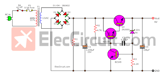
This is another 9v regulated power supply circuit. It uses 2N3055 as the main, so high current up to 2A. If we use 2A to 3A transformer and C1 capacitance is 2200uF.
Its pattern is quite similar to the above circuit. But it is different at the placement of some parts.
Each circuit, the power transistor requires enough heat sink because while it works it is too hot.
Conclusion
We can make a constant voltage DC power supply. To replace a 9V battery and it works well. To reduce battery consumption and high efficiency without any noise enough for normal use.
Read more >> How Op-amp Regulator circuit works
Download This Post
All full-size images and PDFs of this post are in this Ebook below. Please support me. 🙂
GET UPDATE VIA EMAIL
I always try to make Electronics Learning Easy.

i have no idea what you are talking about my suggestion is that you learn correct English and make the site considerably better
regards
this is not meant to be an insult just constructive
Hello, sss.
Thanks for your feedback. I will try to improve my English. I hope you will come back to visit me again.
Hi sss,
Thanks for your feedback.
can I get an item description on all three of them?
I understand the concept but I have never shopped for each individual item before…..
Thanx in advance 🙂
what if i have to make a 5V power supply using the same circuit
what exactly is the function of Q2 in the first one
@9V Regulator 2A-3A current Supply Is it work?
The procedures are quite simple and educative. I find it knowledgeable indeed.