Today I want to share this simple Low Voltage Battery Indicator circuit with my friend. Let’s do it. When the voltage level is lower than recommended by the manufacturer (below 12.4V). To extend the lifespan of the battery, we should always bring it to be fully charged.
We may measure the voltage of the battery with a common voltmeter. But it would be more convenient if we used this circuit instead. It can be used as a voltage monitor for other voltage sources that might have the same problems. By showing on LED and with a buzzer sound alarm.

This post has 2 circuits. The first circuit is used mainly to visualize the principle of a comparator circuit using OP-AMP. Another is a circuit that we currently use. Both circuits can be used to detect the voltage level with a comparator circuit using LM339.
The LM339 Quad Comparator is another type of op-amp specially designed for voltage-sensing circuits, so it is very accurate. It can sense a drop in voltage of 2 or so millivolts, for example when the voltage drops from 12.400V to 12.398V.
Learn more: LM339 datasheet
Two circuits below are:
- First, is a 9V low voltage battery alarm circuit. We tried to build this simple circuit to start learning how the LM339 Quad Comparator works.
- Secondly, is a practical 12V low voltage battery Indicator circuit. We use this circuit almost daily. It is very useful. It gives an alarm when the battery voltage level is lower than the set point.
9V Low Voltage Battery Alarm Circuit
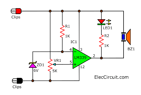
Some circuits may misfunction when a 9V battery powering them voltage level got lower than 8V. By installing this circuit to the output of the battery, if the battery voltage got to lower than 8.3V. LED1 immediately will glow and BZ1 will emit sound.
It is a simple non-inverting comparator circuit. This circuit consists of a few components (6 pieces without any capacitors), an LM339 Quad Comparator as the main component of this circuit, two resistors, a potentiometer, a Zener diode, an LED, and a buzzer.
By connecting both probes to a source—a 9V battery. The current will get into the circuit. There are two important pins of LM339 to see right now.
- Pin 3 is the positive power supply pin (+V).
- Pin 12 is the negative power supply pin (-V).
Then, R1 passes the safe current level to a 6V Zener diode (ZD1). The ZD1 works as a 6V Zener regulator to keep the reference voltage level at pin 4 (inverting input) of IC1.
At the same time, some current from the 9V battery also flows through to a VR1 to the input pin 5 (non-inverting input), also known as a comparing voltage. Both voltages are then compared by IC1; any result will be output to pin 2 (output).
If the voltage at pin 5 is greater than at pin 4, Pin 2 will output a high voltage almost equal to the power supply.
On the other hand, if the voltage at pin 5 is less than at pin 4, Pin 2 will output almost no voltage at all.
Then, we will add the LED1 and BZ1-buzzer as indicators of the output. They are both connected to pin 2 (output) and positive voltage (+V). They will work at the low output voltage only. R2 sets the safe current level for LED1.
What more? The experiment below will help us understand more.
The component list
R1,R2: 1K, 0.25W Resistors
VR1: 5K Potentiometer
IC1: LM339 Voltage comparator IC: Buy Here
ZD1: 6V 0.5W Zener Diode (1N5233)
LED1: 3mm RED LED.
BZ1: 6V-9V Active Electromagnetic Buzzer.
P1, P2: Probes
Perforated board, wires, 8 pin socket for IC1
Recommended: Recycle Free Li-ion battery from E-waste
Experimenting with 9V battery alarm circuit
We assemble this circuit on a breadboard. This circuit will alarm us when the 9V battery voltage level is lower than 8.3V.
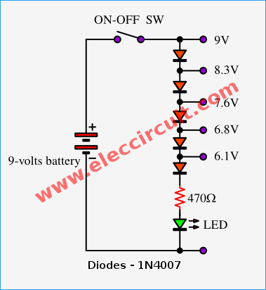
We would need a constant voltage level to test and fine-tune. There are many ways to do this. But let’s use the easiest way possible by using a ladder regulator using diodes.
The silicon diode will conduct when its forward voltage reaches the voltage threshold, which is about 0.7V. It will also keep 0.7V across itself, resulting in a voltage deduction at each level.
We can make use of this situation by taking the voltage output from each diode and turning this circuit into a voltage divider regulator. While the LED acts as a load and the R-resistor as its current limiter.
We use a voltmeter to measure the voltage at each output and the ground. It will result in 9V, 8.3V, 7.6V, 6.8V, and 6.1V, respectively.
Then, we take both probes to an 8.3V output and ground. After that, we adjust VR1 until LED1 glows and BZ1 emits a sound.
Because when we adjust VR1, the voltage drop across VR1 or pin 5 is lowered to below 6V (the reference voltage). The internal circuit of IC1 outputs a very low voltage, sometimes even close to 0V. So, the LED1 and BZ1 get a higher voltage compared to the positive voltage (+V) and the output.
To be sure, let’s move the probes back to 9V again. LED1 and BZ1 should not be working.
On the other hand, if we moved the probes back to 7.6V or 6.8V, respectively. The LED1 will glow again, and the BZ1 will immediately emit a loud noise.
This circuit can be used with a voltage level of about 6.1V to 18V. because we use a 6V Zener Diode. For example, to use a 7.6V voltage, just adjust the sensitivity of the circuit by changing the comparing voltage with a VR1.
In addition, adapting some components can be very useful if you wish to use this circuit at an alternative voltage level. Because the LM339 can be used with a wide range of power supply voltages from 2V to 36V at 0.8mA.
The video below shows the testing of this circuit.
Here is a video of electronics more that makes this project worked very great. Thanks a lot.
12V Low Voltage Battery Indicator Circuit
This circuit will alarm when the battery voltage gets lower than 12.4V. We want to use a 12V 8A water pump (2000GRH Model) in the garden which has no AC electricity. So, we will use a 12V 45Ah Lead-acid battery instead.
Lead-acid batteries are still popular because they are commonly used in cars or motorcycles. So it is easy to buy and cheap. According to my experience, we might be able to use this battery for up to 6 years. It is well worth it. And importantly, it is easy to recycle at a general recycling store. In exchange, we will receive $12.
Of course, the battery has its own lifespan. But what could we do to extend its lifespan even further? There are two important things that we should do:
- Preventing the battery’s temperature from exceeding 50 degrees, which if used normally, it would not get that hot. It should not be placed near a heat source or in direct sunlight.
- Always maintain a voltage greater than 12.4V. Usually, when we leave the battery idle, the voltage level will gradually decrease. Because of its natural discharges, if left for a long time, the battery will deteriorate even faster. Therefore, we should always charge it to keep the voltage at 12.4V or higher. Even when not in use, it should be charged with a low current of about 0.1C.
How it works
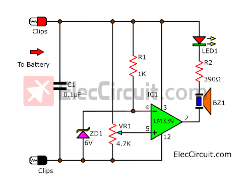
We will make some changes to the first circuit. Because the first one tends to malfunction.
First, connecting the unused input pins to the ground will stop any oscillation of LM339.
Secondly, add C1 across the positive and negative power supply. This capacitor will act like a miniature battery that keeps supplying stable power during the spike voltage.
Thirdly, lower the buzzer size. And connect the buzzer in series with LED1 and the resistor. This in turn will decrease the output current wasted.
Learn: series circuit
How to builds
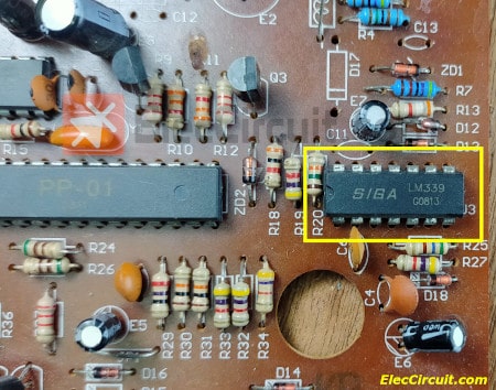
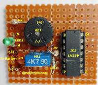
In this circuit, we reuse the LM339 and most of the components from the PCB in the appliance that we no longer use. It is one good way to recycle.
The Components List
R1,R2: 1K, 0.25W Resistors
VR1: 4.7K Potentiometer
C1: 0.1uF 50V Ceramic capacitor
IC1: LM339 Voltage comparator IC
ZD1: 6V 0.5W Zener Diode (1N5233)
LED1: 3mm Green LED.
BZ1: Active Electromagnetic Buzzer 5V.
P1, P2: Probes
Perforated board, wires, 8-pin socket for IC1
Recommended: If you are a beginner, read Electronic components list with images.
We assemble all components on perforated PCB board and solder its pin connections according to the wiring PCB layout.
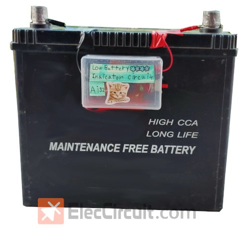
We then install this circuit into the plastic box to protect it from the outside elements.
Then, tune it using a variable DC power supply by setting the power supply voltage to 12.400V.
And connects the probe to that power supply, then adjusts VR1 until LED1 and BZ1 are emitting light and sound.
After that, stick the box and wire it neatly to the 12V battery. This is the prototype of the 12V Low Voltage Battery Indicator Circuit that is finished.
This circuit is simple but works great. It can warn us when the battery is lower than 12.4V by using BZ1 noise and LED1. It also consumes a very small amount of power. If you are annoyed with the sound, you may put a switch in to turn off the circuit.
Download This Post
All full-size images and PDFs of this post are in this Ebook below. Please support me. 🙂






Hi!
Sorry, but may it be the false pins in the image of the Voltage Indicator?
It’s the false way round, 5&4, 7&6 and so on…
The Voltage of reference should be on the -Pin and the Voltage you want to comparate on the +Pin, shouldn’t it?
Please give me a answer if it’s like i sad, or if not tell me why, because if i build it like in the picture all the LEDs flash!
Oh, sorry i’ve looked somewhere else it’s right, but why isn’t it working?
Ok, i found the false…
i like what you allays polished. i will like some projects that you have already design
It works great, but when kept connected continuously to 9 v battery, battery is draining fast , can you suggest what can be done to avoid this circuit not to drain battery fast when kept connected on continuous on to battery
Hi,Jonas Strauch
Thanks for your feedback.
Hi, I was very interested in your info, however, I had difficulty with grammar. Is it possible to correct the following: When the input voltage is higher than 6-volts will cause high at output but LED1 will still not works and not soud buzzer sine each leg them are connected to positive suppy and output pin. But when the input voltage is lower than 6-volts then will makes LED1 glow brightly and buzzer emit sound. Which we can set the level voltage input with adjust sentility of circuit by control VR1
Only bbecause I want to understand the LM339 and how the correct the voltage setting using VR1.
Thanks.
Hi , how to change this circuit to alarm when voltage reaches 11.8 volts and alarm goes off when voltages reaches 12.4 volts
thank you
Hi!, I’m looking for the materials to build this circuit and I can’t find here in Argentina the 1N5233, Do you think that can be replaced with the 1N753? The spec are very similar 6.2V 0.4W
Thanks for your help!!
I would like a more definitive identity for the LM339 chip used in the 12v lead acid battery low voltage alarm. When I looked at Mouser there were a dozen LM339s with different labels. Which one should be used for this project. Thanks. Tedd Lovell
Hi Tedd Lovell,
Thanks for your question.
I think you may use LM339N better because it is cheaper. I like it.
What component values are needed for 24 volt system? I need to monitor a 24 volt system with voltage alarm at approximately 22 volts Thanks