If your ring Telephone is low. How to solve the problem? You should use a Telephone Ring Amplifier circuit. It can increase the signal of the telephone lines up. There are many ways to do this. You can look at below four circuit ideas.
Telephone repeater circuit project
The telephone repeater circuit or The call signal peripheral circuit to the loud than the original. It’s a circuit that we design follow the request. One of my friends. His ears are a bit tight as such phone rings only. He does not quite go ahead.
Therefore, it is my responsibility, To help design. For the amplify the signal from phone loud sound more than ever. I used to attach circuits with a buzzer or an electric bell, to act as the increase loud sound of bell telephone. For some of you who want to use this a circuit. If it is modified by change light bulb replace the electric bells as well. When the call came in, the lamp will be flashing by the call signal.
The working of a circuit
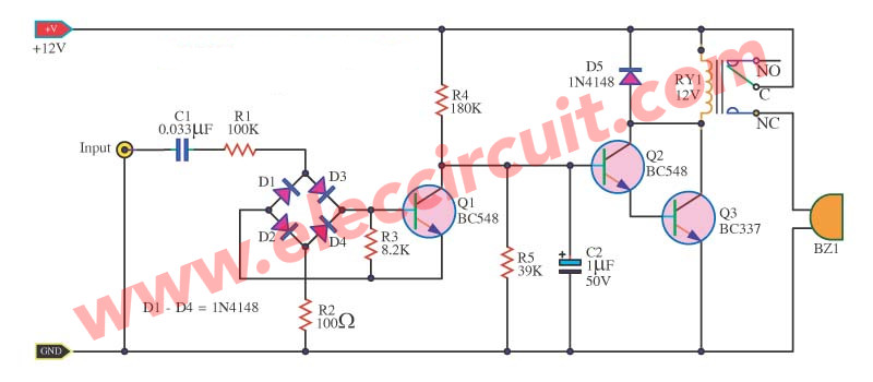
We connect the input signal directly from the telephone line. However, since a circuit input impedance is very high so it is not loaded the telephone circuit, for enter the call signal to the Q1 work,
Therefore, The collector voltage of Q1 reduced until Q2, and Q3 stops working, The contract of relay is connected to the electric bell and lamps as needed.
How to make it.
This project can build easily by youself. In figure 2 is the PCB layout as real size. and right side is the components layout. Which if you can use the Universal PCB board as well because it has a few parts in circuits.
Figure 2 PCB layout and all components layout of this projects.
Electronic parts
C1___________0.033uF 600V Polyester Capacitor
C2___________1uF 16V Electrolytic Capacitors
R1___________100K 1/4W Resistor
R2___________100 ohms 1/4W Resistor
R3___________8.2K 1/4W Resistor
R4___________180K 1/4W Resistor
R5___________39K 1/4W Resistor
D1-D5________1N4148 75V 150mA Diodes
Q1-Q2________BC548 45V 100mA NPN Transistor
Q3___________BC337 50V 800mA NPN Transistor
RY___________Relay 12V normal closed
Easy Telephone Amplifiers circuit
This is an easy telephone amplifier circuit. It will increase the signal of the telephone lines up. Then, drive the relay to controls the large electric bells that louder than a general phone. This circuit is modified from the speaker protection circuit, so easy and cheap.
How it works
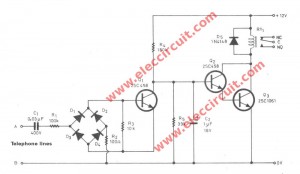
Figure 1 the circuit diagram.
After that we connect the A and B point to the telephone lines. In normal state that not have the incoming call, the DC voltage +48 volts will cannot through to the capacitors-C1, so no current flow to D1-D4.
Thus, no bias current to the base lead of the transistor-Q1 , so it doesn’t conduct current . While,the voltage at the collector of Q1 will rises, cause the transistor-Q2 get bias and conduct current. So, the Q2 also conduct current, to apply the coil of relay-RY1 cause it works.
When it has the incoming call into the telephone lines which is an AC signal about 100 Vp-p. This signal will through C1 to the diode bridge (D1-D4), the positive rage will through to D1, R3, D4 and R2, but the negative will through to D3, R3, D2 and R2.
Therefore, the transistors-Q1 get a bias and conduct current, until appear the voltage at the collector lead will be very low, cause both Q2 and Q3 doesn’t conduct current, results not have the current flow to coil of RY1. Thus RY1 so stop.
Application
This circuit have a few parts so you can easily build it on the universal PCB . Then,check for error. If the circuit is complete. Next,connect both A and B point to the telephone lines. While,we will hear the relay works.
After that, Calling your number,then hear the bell ringing and relay-RY1 will stop working.
The application we select the contact NC-C to control the electric bell. Or can install it on the top layer of the house. When ringing phone downstairs rang. the electric bell on top layer will loud as well.
The parts you need.
1. Q1,Q2___2SC458 or 2SC1815 or similar___45V 100mA NPN Transistor
2. Q3______2SC1061 or TIP41 or similar___40V 4A NPN Transistor
3. RY1_____Relay 12V 1 contact.
4. D1-D5___1N4148____75V 150mA Diodes
5. C1______0.033uF 400V___Polyester Capacitor
6. C2______1uF 25V_______Electrolytic Capacitors
7. R1______100K_____0.5 W Resistors tolerance: 5%
8. R2______100 ohms____0.5 W Resistors tolerance: 5%
9. R3______10K_____0.5 W Resistors tolerance: 5%
10. R4______180K_____0.5 W Resistors tolerance: 5%
11. R5______39K_____0.5 W Resistors tolerance: 5%
Telephone bell ringer circuit using IC-KA2411
This Telephone bell ringer circuit for generating the electricity bell in the old telephone. This circuit is relatively loud. so can use to replacement the same ringer or the original telephone may be lost. We do not need a new phone.
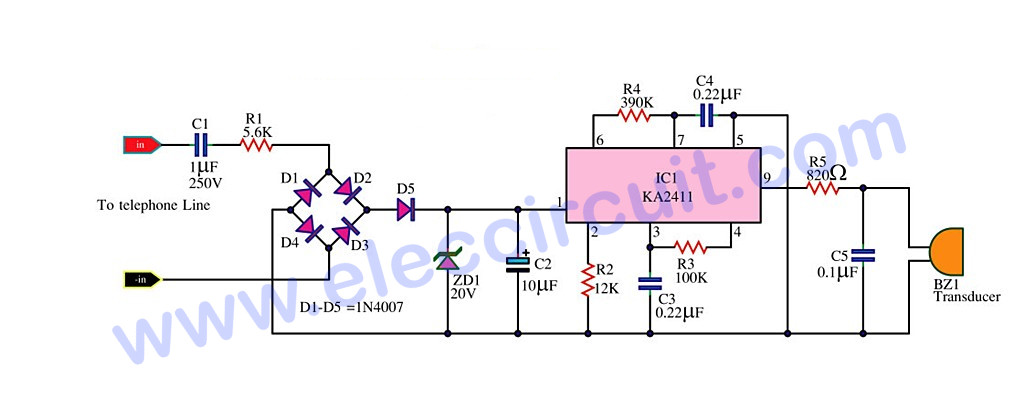
This circuit is easily to build, because it uses a single IC as shown in figure below.
Before you read working this circuit. I suggest a simple ideal is:
Detect ringing signal tone with light and sound
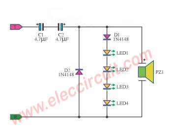
The detect ringing signal tone circuit with light and sound.It is easy to use and good quality, Do not enter the power supply. Which as Detect ringing signal tone circuit Or ring tones on the telephone line, a signal incoming calls.
When an incoming call,When an incoming call, The C1, C2, will act as a coupling signal AC Volt to diodes D1, D2.Signal voltage is reduced down to approximately 10V.By D2 to detect, only a negative signal,One extreme to the other end of the wire loop.The D1 detect a positive signal, and the 4 LED. Flashing light attached to it,with frequency of the ringging tone.Which is about 20 Hz. and piezo speaker, show the audio beep .. beep, followed by a tone frequency of the ringing.
LED can be connected in series to increase, but less in proportion to the light.The circuit uses power from the telephone line.
Then come back to see the Loud Ringer circuit for the Home Phone.
How this circuit works
The called signal from the telephone lines is entered through C1, R1 Come to the bridge diode circuit D1-D4, D5 is the positive voltage at 20V supply to pin 1 of IC1 that KA2411 or CS8205 as the Telephone Bell Replacement IC.
When IC1 is given the supply volt as I said, it will generator a ringing signals through the R5, to drive the Piezoelectric transducer BZ1 be a bell tone out to hear.
The ringing tone light, we may reduce the R5 for low down.
We hear the sound of the Oscillator 2 series, which differ by the output frequency chops to be a frequency generator circuits. Which consists with R3, C3 is low.
F-LOW = 1/1.289 R3.C3
For a maximum frequency is calculated from.
F-h1 = 1/1.504 R4.C4
The second highest frequency is calculated from
F-h2 = 1/1.203 R4.C4
The parts of circuit
IC1__________KA2411 or CS8205___Telephone Bell Replacement IC
D1-D5________1N4007___1000V 1A Diodes
ZD1__________20V 0.5W Zener Diode
R1__________5.6K 1/2W Resistor
R2__________12K 1/4W Resistor
R3__________100K 1/4W Resistor
R4__________390K 1/4W Resistor
R5__________820ohm 1/2W Resistor
C1___________1uF 250V Polyester Capacitor
C2_________10µF 25V Electrolytic Capacitors
C3___________0.22uF 63V Polyester Capacitor
C4___________0.0022uF 63V Polyester Capacitor
C5___________0.1uF 63V Polyester Capacitor
BZ1__________Piezoelectric Transducer
How to builds
You can builds this projects with make the PCB before and then puting All components in this circuit (as Figure 2)except of the piezoelectric transducers can be assembled into a perforated board. You should check the accuracy. Then try to connect the telephone lines, then call come in, will be have hear the ringing tone, if the sound is not impressive, you can change the RC with formula given above.
Figure 2 PCB and the components layout
LM358 Telephone pickup circuit with amplifiers
This is the telephone pickup circuit small amplifiers for To expand the voice conversation louder. or intercepted phone call. It use pickup telephone and LM358 op-amp IC as preamplifier and LM386 out to speaker and use 9V battery Low power consumption.
The working principle
The complete circuit of the The telephone pickup amplifier is shown in Figure 1 the working start with a signal from magnetic pickup will entered in to J1-Jack to amplify amplitude up by preamplifier. Which is serves by IC1/2 and IC1/1 as LM358 OP-AMP IC will get voltage biasing from input into half of power supply, to audio signal swing to be balanced, both positive and half negative half wave. By resistors R4 and R5 There is capacitors C6 pull AC signal to ground to purity voltage on the AC impedance is low.
Figure 1 The complete telephone pickup amplifier.
The pickup signal will be connected through C2 to first preamplifier IC. Which R3-resistor is set an input impedance of circuit about 100K ohms. This preamplifier serves as amplify weak signal into higher signal, And is also a sound filter, By sound frequency of telephone there are in range of 300 Hertz to 3 KHz.
The working of filter circuit wil be feedback on RC form. Whic include capacitors-C3 and R1-resistors. The cut off frequency of circuit can be calculated from relations.
Frequencies (f) = 1/(6.28xRC) Hz….(1)
By R = resistance (ohm), and C = capacitance (F) see in circuit we use 220pF capacitor and 270K resistor, then calculated will be:
the Cut off frequency (f)
= 1/(6.28x270x10/3x220x10/-12)
= 2680 Hertz
The pickup signal will is amplified by the preamplifier set of IC2/1 and IC1/1, both section to high gain. The output signal from preamplifier will be send through C7 capacitor to amplify out to speaker. The LM386 audio amplifier chip is well known in as an amplifier and controlled level audio by VR1-volumes of a horseshoe.
GET UPDATE VIA EMAIL
I always try to make Electronics Learning Easy.
Related Posts
I love electronic circuit. I will collect a lot circuit electronic for teach my son and are useful for everyone.


Hello,
I am looking for the schematics for a cell phone signal repeater (s) 850 Mhz. Can you halp me?
Regards,
Eugene
I am looking for the schematics for a cell phone signal repeater (s) 850 Mhz. Can you halp me?
Regards
Hi,Aloisio Santos frc
Thanks for your feedback.
Now I don’t have this as you need.
I’m sorry.
If I have them will tell you.