Do you want a 3A voltage regulator circuit? Before we often you LM350. But now we may use others. Some use LM2596 circuit.
It is suitable for easy and convenient use as a step-down switching regulator. Some called a buck converter circuit.
LM2596 datasheet
Here are why I like them.
Drives 3.0 A load with excellent line and load regulation.
Runs on a switching frequency of 150 kHz. So, we can use a smaller sized filter than lower frequency switching regulators.
Requires a few external components. So, smaller circuit.
Imagine You are using LM350 is smaller and not hot. I like the LM2596.
Features
Let’s read the features. I may say wow!
There are 2 versions. Fixed and Adjustable voltage Read more below
- Fixed output voltages of 3.3V, 5V, 12V. Requires only 4 external components
- Adjustable Output Voltage Range 1.23 V − 37 V
- 3.0A Output Load Current (Guaranteed)
- Wide Input Voltage Range up to 40 V
- 150 kHz Fixed Frequency Internal Oscillator
- TTL Shutdown Capability
- Low Power Standby Mode, type 80 uA
- Perfect protection circuit. Thermal Shutdown and Current Limit Protection
- Internal Loop Compensation
Pinout
We can use them with 2 package.
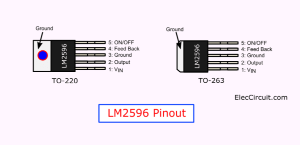
- Standard—5-lead TO-220 package with
several different lead bend options - Small—5-lead TO-263 surface mount package. (Now we often see this
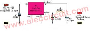
LM2596 Fixed voltage regulator
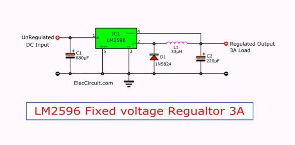
In fixed voltage regulator version. See the circuit above.
We can set output voltage with changing IC follows.
- LM2596-3.3 for 3.3V output.
- LM2596-5.0 is 5V output.
- LM2596-12 is 12V output.
And we should other appropriate components too.
- C1 should become 330uF (when using LM2596-3.3, LM2596-5.0).
or 180uF (for LM2596-12) - L1 = wire coil inductor, be valuable 33uH (for LM2596-3.3, LM2596-5.0) or 68uH (for LM2596-12)
LM2596 Adjustable Output Voltage Regulator
Now we see most people use LM2596 in adjustable out voltage regulator. It is easy like LM350. See in the circuit below.
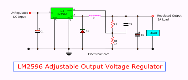
Please ensure that the input voltage is higher than the output voltage.
In the general input is 3.2V to 40V. And the output is 1.23V to 35V.
We just only add R1 and R2 to Feed back lead. To control the output voltage.
Vout = VREF{(1+(R2/R1)} where VREF = 1.23V
R1: 1K
R2 = R1{(Vout/VREF)-1}
Parts list
C1: 470uF 50V Electrolytic
C2: 220uF 50V Electrolytic
D1: 5A, 40V Schottky Rectifier, 1N5825
L1: 68uH
R1: 1K, 0.25W 1% resistor
C3: 0.0033uF
You are reading here. You may want to build a good DC Variable power supply, right?
Let’s read below.
You may also like these:
- 0-50V 3A Variable power supply
- 0-30V 20A High current adjustable voltage regulator circuit
- LM2575 Simple switcher 1A step down voltage regulator
- 0-30V variable Power Supply at 3A
DIY LM2596 adjustable voltage switching regulator
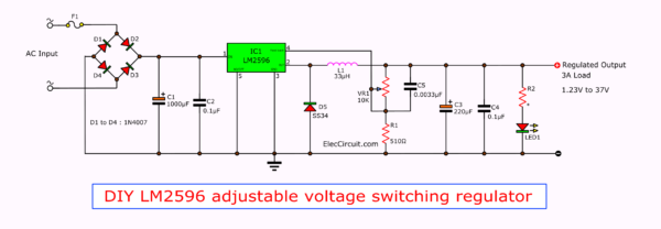
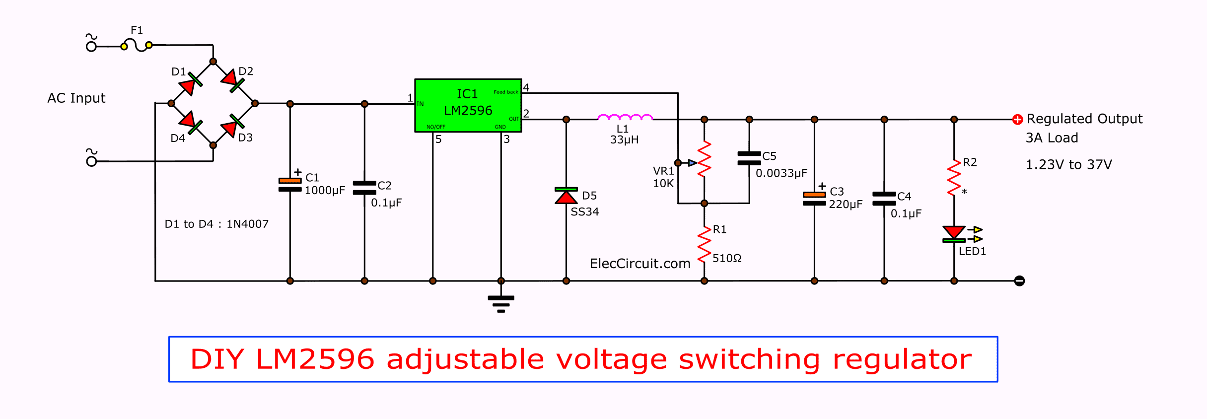
Here is DIY LM2596 Adjustable Voltage Regulator Switching Power Supply circuit. The Output adjustable 1.23V to 37V at 3A current.
It is a real circuit in use.
See the circuit diagram below.
Circuit ideas that you can get useful
How LM2596 circuit works
Here is the step-by-step process:
The AC voltage from the transformer gets into the circuit through the AC input terminal.
First, AC voltage flows through fuse F1 to protect against overload current because of the short circuit at the output.
Then, AC voltage comes into the bridge diodes (D1 through D4) to be rectified from AC voltage into a DC pulse.
Next, both capacitors, C1 and C2, filtered that DC pulse to a more stable DC voltage. Or a DC voltage input to IC1.
This may look familiar to some; see the Unregulated power supply. principle for more understanding.
We can set the rough maximum of the output voltage by changing a few components.
- If you want the max output to be 37V, use 1,000uF 63V C1, and the AC transformer should be 28V, or you can apply up to 40V DC voltage directly into the input.
- But if you want the max output to be 15V, use 1,000uF 25V C1, and the AC transformer should be 12V, or you can apply up to 18V DC voltage directly into the input.
- Or if you want the max output to be 30V, use 1,000uF 50V C1, and the AC transformer should be 24V or you can apply up to 33V DC voltage directly to the input.
4. LM2596 get the DC voltage. It keeps a constant voltage in a switching regulator. It needs to have a helper are:
- L1 is a special inductance, which acts as energy conversion.
when you look a switching regulator need have it.See: How to make inductance easily! - D5 is the Schottky diode, which plays a continuous role in the circuit.Check: you cannot check this type diode in normal use this tool: The Diode tester circuit.
- C5 is Feedforward Capacitor. It keeps a more stable voltage of the circuit. When the output voltage is more 10V up.
5. The output voltage of R1 and W1. We can calculate by the following formula:
Vo=1.23(1 W1/R1)
We notice formula look simar: LM317, LM350 and LM338
6. C3, C4 is the output filter capacitors.
7. LED1 is 8mm white LED. Its brightness can roughly indicate the output voltage.
If the brightness is too bright, you can increase the resistance of R2 properly.
Look… using the limiting current resistor
Parts list
IC1-LM2596 switching regulator circuit
F1- 3A fuse
D1-D4: 1N4007, 1000V 1A diodes
D5: SS34, Schottky diode or 1N5825
C1: 1000uF 50V Electrolytic, See text.
C3: 220uF 50V Electrolytic
C2, C4: 0.1uF 50V Ceramic
C5: 0.0033uF 50V Ceramic
LED1: 8mm white LED
R1: 510 ohms 1%, 0.25W Resistor
VR1: 10K potentiometer
L1: 33 uH coil
R2: see text
What is more
At times, you may wonder like me.
Can use 1N4007 in 3A power supply?
Watch video this circuit can give current more 3A.
Why?
It runs with very high frequency. So, use energy lower and fast. Then, keep the power in the inductor. To reduce a load current of a diode and more parts.
You like this?
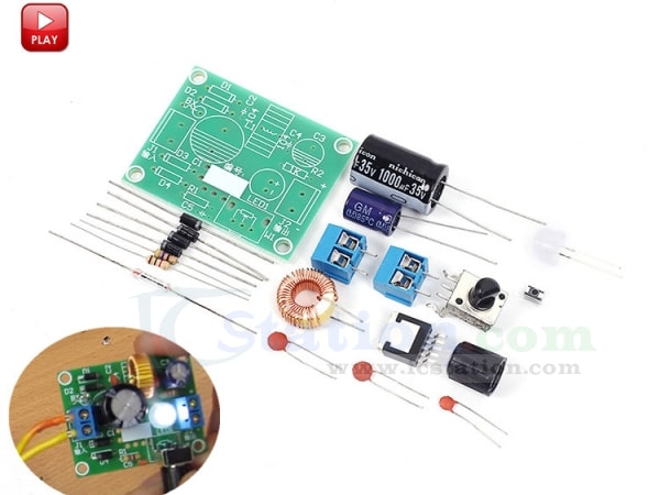
If you are interested in this project, do not wait. It is surprisingly cheap. And free shipping Convenient with PayPal payment
Buy here!
Not only that Do you see other 3A switching supply IC chip? Below!
LM2673 -5V 3A Switching Voltage Regulator
This is the DC switching regulator Voltage 5V at current 3A. It is make for digital circuit. The important part of the circuit is LM2673, it is 3A Step-Down Voltage Regulator with Adjustable Current Limit. The LM2673 is Simple and easy to design with using off-the-shelf external components.
The LM2673 series of regulators circuits that main function as a step-down or buck switching regulator, can drive up to 3-A load with excellent line and load regulation. It has High efficiency 90% up, use a low ON-resistance DMOS power switch inside.
The series consists of fixed output voltages of 3.3 V, 5 V, and 12 V and an adjustable output version. Now we use 5V 3A switch power supply using LM2673.
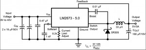
This circuit complete design that a minimum number of external parts. A high fixed frequency oscillator up to 260 kHz allows the use of physically smaller sized components. A family of standard inductors used with the LM2673, are available from several manufacturers to simple the design working.
More features include to reduce the input surge current at power on by adding a soft start timing capacitor to soft turn on this. The LM2673 series will has built-in thermal shutdown and resistor programmable current limit of the power MOSFET so switch to protect the device and load circuit. The output voltage has a ±2% tolerance. The clock frequency is controlled to within a ±11% .
Feature Lists
- Efficiency Up to 94%
- Simple and Easy to Design With (Using Off-The-Shelf External parts)
- Resistor Programmable Peak Current Limit Over a Range of 2A to 5 A
What’s more? You can look other power supply circuits
Please see circuit diagram and read more source.
https://www.national.com/pf/LM/LM2673.html
GET UPDATE VIA EMAIL
I always try to make Electronics Learning Easy.
Related Posts

I love electronics. I have been learning about them through creating simple electronic circuits or small projects. And now I am also having my children do the same. Nevertheless, I hope you found the experiences we shared on this site useful and fulfilling.


I want to make “DIY LM2596 adjustable voltage switching regulator” with 3A (max) current and 13.2 V output to charge Lead Acid Car Battery. I have a question: in case the battery is in fully discharged connection, it may draw higher current , in such a case will the circuit limit the current to 3 amps by lowering the output voltage ? OR the LM2596 wil get burnt?
Hello VK Singh,
Thanks for your question.
Yes, you can use it. Because It has overload protection, see in the datasheet.
But I think you should put overcurrent, too. At first, the battery uses a high current.
I feel interested in this circuit. But I am very busy. I am sorry cannot draw a circuit for you.
Thanks
Hello! I am interested to build an symmetrical power source +/-15V with LM2596 and his homologue/pair for the other arm. Can you share with me what circuit to use in tandem with LM2596 and which is the diagram that I have to use it?
Thank you!
Hello Mihail Necula,
Thanks for your visit. I am happy that you like LM2596, too.
Do you want a Dual 15V output voltage? (+15V GND -15V).
See in the datasheet: https://www.datasheets360.com/pdf/-2919773549615076541?query=LM2596&pqid=107399538
You may use Flyback Regulator with ± Outputs like this https://www.datasheets360.com/pdf/-5249528882279440361?query=LM2577&pqid=107399582
Honestly, I haven’t tried it yet. But I believe you have the ability to experiment and do it for sure. Don’t forget to share your story, I will wait.
Thanks
Apichet
Ps: See more: https://www.eleccircuit.com/lm2577-5v-to-12v-dc-converter-step-up-voltage-regulator/
can LM2596 make step up?
Hello, norman,
Thanks for your visit. Normally, datasheets often use LM2596 as Output Series Buck Regulator.
But I believe We might be able to modify it as a Step-up DC converter circuit.
you have said that “AC voltage from the transformer gets in the circuit.” what do mean by “from the transformer”??
how mush is the value of the ac voltage from the transformer ?
3.2V to 40V ac ??
Please read: https://www.eleccircuit.com/regulator-switching-dc-to-dc-step-down-voltage-with-lm2596/#How_LM2596_circuit_works 🙂