Have you ever used an LM324 circuit? We may see them in many circuit diagrams. Because they are low-power quad operational amplifiers with true differential inputs.
They require a battery or single-polarity supply (positive and negative only). In over a very wide voltage range. The working voltage is definitely 3V. Nowadays, it is more convenient to use a 3.7V lithium battery. It works well with CMOS ICs because it consumes low current.
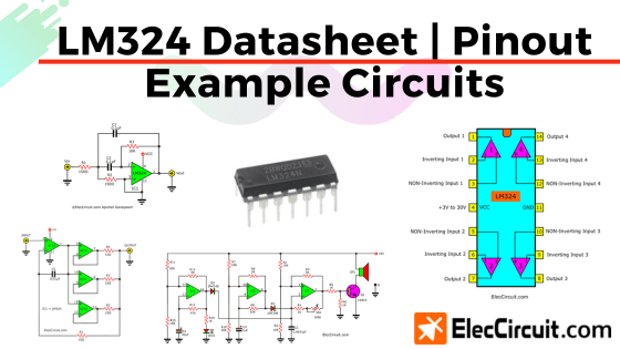
About LM324
It is more convenient than LM741, which has only one op-amp and has higher power dissipation, so it is used in many applications such as oscillators, amplifiers, filters, etc., including comparators, but its efficiency is lower than LM339 comparators directly.
LM324 Pinout
The single DIP package has 14 pins and four op-amps inside. You can use only one of the op-amps or all four. The current consumption is unaffected by the power supply voltage.
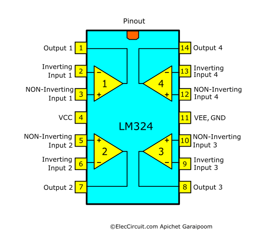
Here is pin connections of LM324 OP-Amp, LM224, LM2902
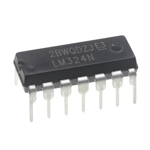
Photo by ALLECIN Store Buy LM324 at Amazon.com: HERE
Note: There are affiliate links on this post. This does not change the cost of the item for you. Thanks for your support.
Feature specifications
- Quad Op-Amp, Unity Gain Bandwidth 1.3MHz
- Wide power supply voltage range: Single Supply 3V-32V, Dual Supply ±1.5V to ±16V Eg. Imagination uses a single 3.7V Li-on battery as a power supply. You can also use two 1.5V AA batteries.
- Use low power supply current (minimum): 0.8 mA.
- The normal output current for each op-amp (at pin-output to the ground) of: 20 mA typical (10 mA minimum).
- The output current that flows from the positive supply to the output pin: is 8 mA typical (5 mA minimum).
- The maximum voltage gain (typical): is 100,000.
- Large voltage gain: 100 dB
- Low input offset voltage: 5 mV max.
- True Differential Input Stage
- Set the gain by setting feedback resistors between the output pin and inverting (-) input.
- Slew Rate 0.5V/us, Input Offset Voltage 3mV
- Input common-mode voltage range includes ground
- Short Circuited Protected Outputs
Power supply for LM324
In circuit diagram below shows single supply and split supplies for LM324. We can use only a 3.7V Li-ion battery or two 1.5V batteries. It is an OP-AMP that uses very low voltage.
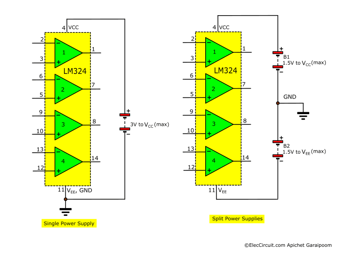
But when using this IC, be especially careful. The polarity of the power supply is different from other ICs, so be careful not to reverse the polarity. Also, be careful not to let the output touch the positive power supply or ground; otherwise, it will be damaged immediately.
Interface Circuits using LM324
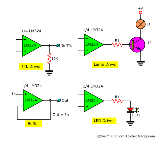
Here are examples of interface circuits using LM324, with TTL digital, Buffer, LAMP Driver, and LED driver.
The LM324 circuits application
The best learning is doing it. I am slowly learning in anything but when I try to do it I will understand. You may be the same as me. The LM324 has numerous circuit applications. We can use it in many projects, including transducer amplifiers, DC gain blocks, and all the conventional op amp circuits.
How to increase the output current
When we have a low current output of OP-AMP, we cannot use any circuit output. We can increase the OP-AMP output current by this. In-circuit the OP-AMP IC-LM324 up current to 85mA size max.
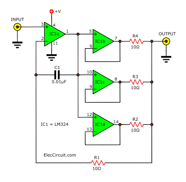
The op-amp output current can generally be in the range of 20 to 40 mA.
and The LM324 has numerous applications. Quad/ 1MHz/ Operational Amplifiers for Commercial/ Industrial/ and Military Applications. You will build a light meter that uses all four OP-Amps in LM324 to form a ladder comparator.
But they can provide an output current of 20mA only.
The LM324 IC number includes 4 OP-Amps. and 3 OP-amp is applied to parallel together. Therefore the output currents up to 85mA, it also has significant short-circuit protection.
The properties of frequency response time from 0 Hz to 200 kHz, the R1-(10ohm), and C1-(0.01uF) are for control of isolates within, and R is the 10 ohms to control the flow of the op-amp for each mean much every op-amp.
LED flasher – Oscillator circuit
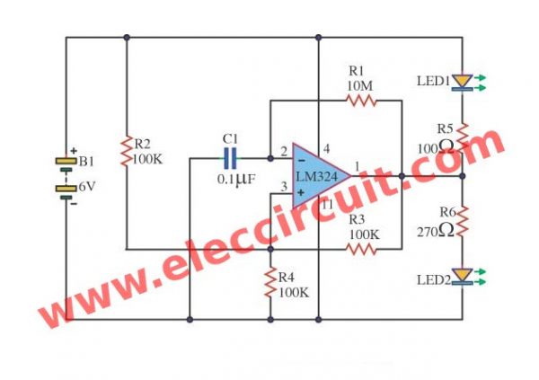
The two LEDs will wink to alternate between a Red LED and a Green LED. At 1 cycle per second. Also, be a Square wave generator circuit. Change frequency by C1.
Cricket sound effect circuit with buzzer
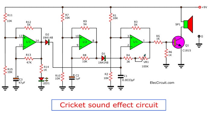
It is a sound effects generator using LM324 op-amp and emits a buzzer. And they sound similar the crickets are singing a couple we’ve ever heard. In-circuit, we don’t use any microcontroller ICs so you can build easily them and also cheaper
1kHz bandpass filter circuit
When you want a simple bandpass Filter circuit at a Frequency 1KHz. We recommend this circuit. Because it uses LM324 op-amp highly popular.
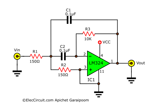
We can change other frequencies with R1, C1, C2, and R2.
Logic Digital Tester
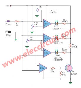
This is Logic Digital Tester Circuit. It uses the level input about 5V and use the integrated circuit LM324. Be Main Part electronics perform Drive All LED. Then use Current very low about 10mA…
1.5V battery tester circuit
It can measure the voltage of the 1.5V battery, AA or AAA. In a decimal point. How? Easy to use by reading LEDs display,
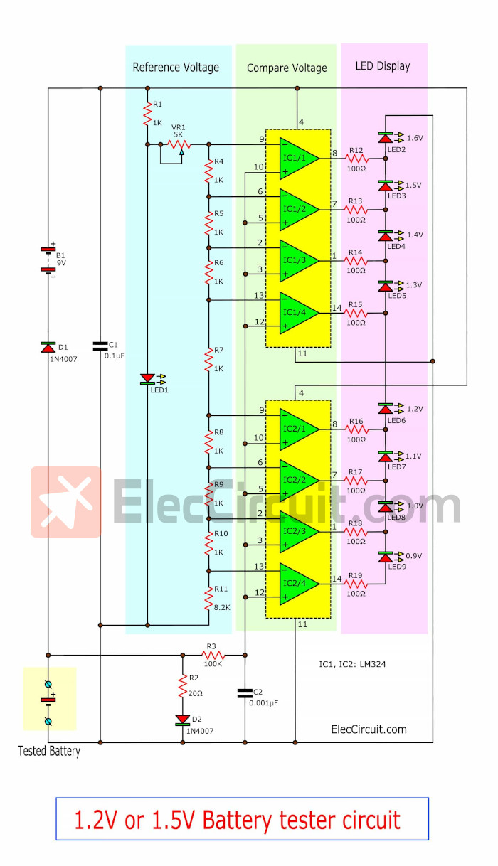
Accurate because the IC-LM324 is a voltage checker. Measure all battery of any kind, whether plain battery or rechargeable battery(1.2V).
Food & Water Salinity Tester Meter circuit
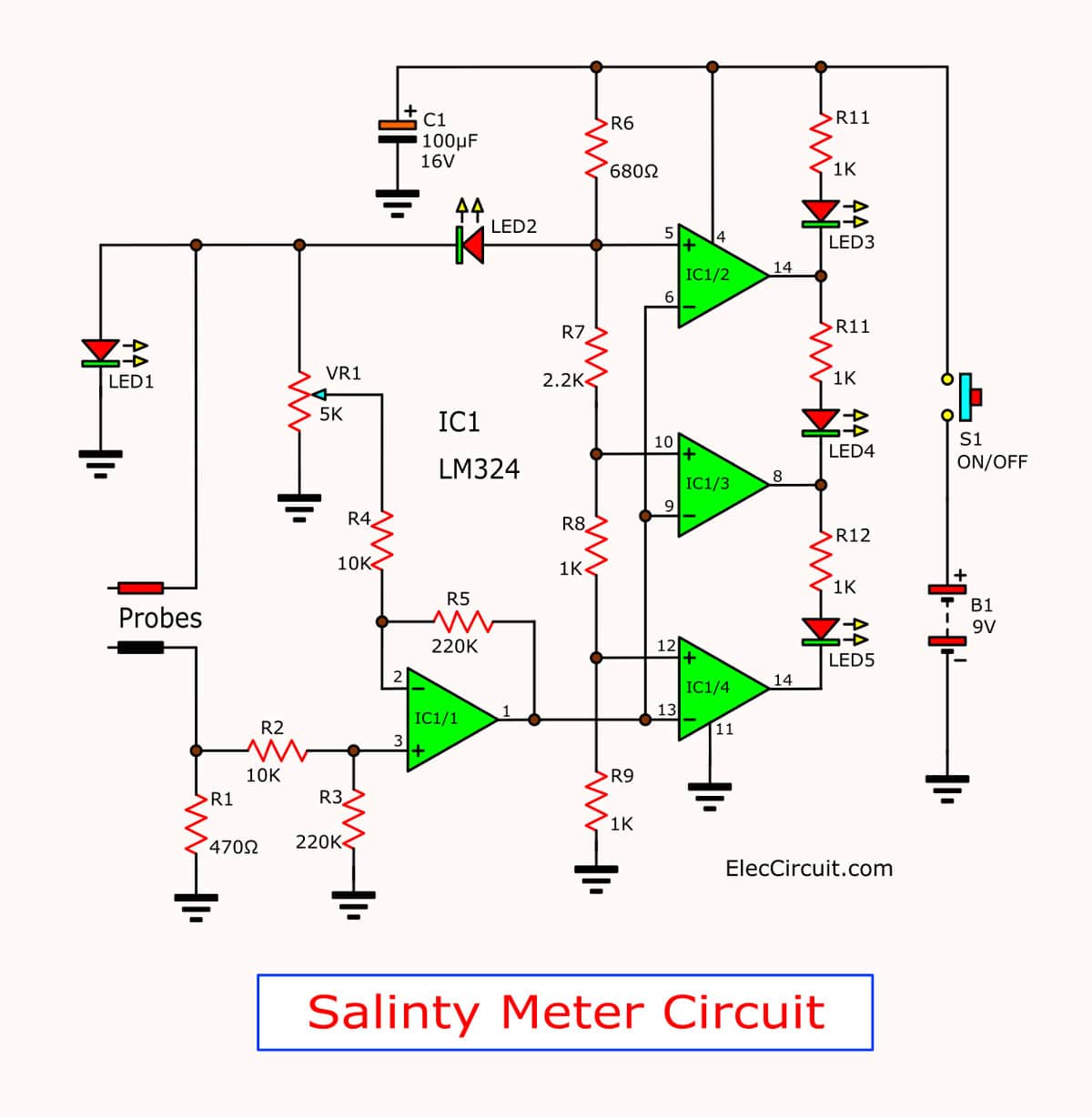
Why should use it? Eating too much salinity not good for health. You may buy a new one of a salt tester. But creating it is pride. And the use of electronic learning time LM324 too.
GET UPDATE VIA EMAIL
I always try to make Electronics Learning Easy.
Related Posts

I love electronics. I have been learning about them through creating simple electronic circuits or small projects. And now I am also having my children do the same. Nevertheless, I hope you found the experiences we shared on this site useful and fulfilling.
Increase output current of LM324 circuit inverting inputs and non inverting inputs reversed…
Hi hakan,
Yes, You see correctly. I just updated it now.
Thanks a lot, a great friend.
Apichet
I was wondering if you can help me with a contest excercize. Does anyone have idea what circuit requires these parts:
Resistors, ¼ W:
10 Ω
68 Ω
82 Ω
100 Ω
120 Ω
150 Ω
220 Ω
470 Ω
560 Ω
1000 Ω – 5 pieces
2200 Ω
3300 Ω
3900 Ω
10 000 Ω – 2 pieces
LED’s:
green, yellow, red
Integratred circuits:
7805
LM324N
Source: 9 V
Thanks.
Hello Mladen,
Honestly, I don’t know which circuit these devices use.
If this is important to you. I cannot confirm. But I would like to comment a little.
In list has IC-7805. It may be about digital circuits, use 5V. But I can’t confirm that it works normally. Because I and my daughter haven’t tried it yet. We’re sorry to help you less.
Thanks
I would bet that the lm324n is used as a comparator. So many resistors would suggest that it would be used to test resistors against a known value and light up LED’s to indicate tolerance.
I am guessing here but that seems to be what I would do with those parts.
Regards,
Well The 7805 ic in the list above
is of the family 78xx,which have fixed constant output of 5v 1a
input voltage ranges from 6v…
it can be use on any circuit that requires 5v power supply
Hello, thank you for your explanation, what software did you use to design the circuit?
Hello Mohammand,
It’s my pleasure. I apologize for not being able to answer the name of the software because I promised my benefactor that I would not reveal its name. It is just simple drawing software. I hope you understand me.
Thanks for your feedback.