This are TDA2009 Stereo | Bridge amplifiers. Do you want it? I know why you feel interested in this. Imagine you and friends listen to the favorite music in a private room. It is a true paradise.
Because you have a quality Hi-Fi system like this. This is a class AB audio power amplifier. The greatest output power of 10W + 10W. And, it is suitable for 4 ohms loudspeaker.
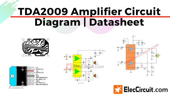
TDA2009 Datasheet
The TDA2009A is class AB dual Hi-Fi Audio power amplifier. It assembled in Multiwatt package, specially designed for high-quality stereo application as Hi-Fi and music center.
We can see its shape here.
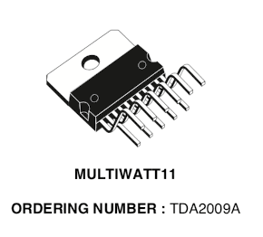
Found out TDA2009 at Amazon.com Here
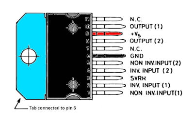
And We can see the TDA2009 pinout here.
You like feature circuit, right?
- DC power supply: 8V to 24V at 1A to 2A
- The output power rate.
10W RMS/channel, 4 ohms load, 24V DC power supply.
6W RMS/Chanel, 8 ohms load, 24V DC power supply.
4W RMS/channel, 4 ohms load, 12V DC power supply. - S/N ratio: more 75 dBA re. 10W output.
- Frequency response: 10Hz to 50kHz -3dB.
- 0.351% distortion at a frequency 1 kHz
- Gain: 36dB.
- Input: 100mV for full output.
Is it nice? Do you like it?
The TDA2009 Stereo Amplifier Circuit Works
The circuit is very clear. Most circuit diagram is in the TDA2009 module.
Every component helps the circuit works well.
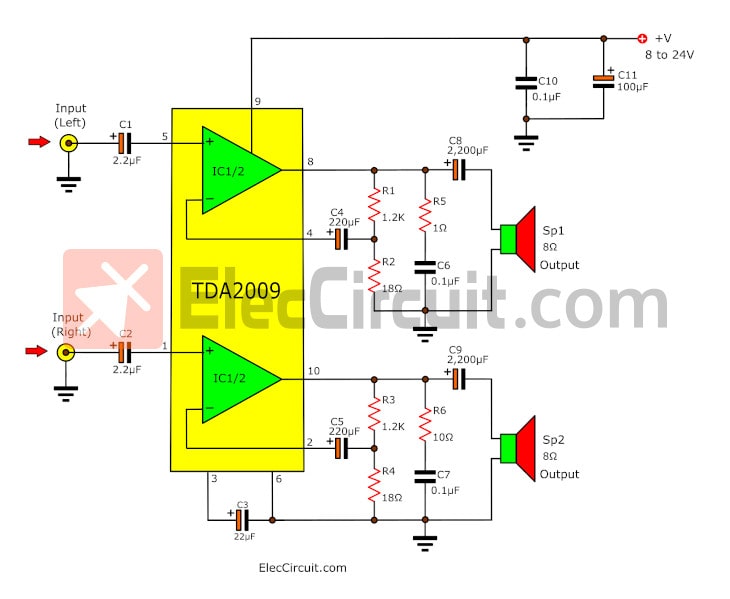
First of all, enter the power supply into the circuit. Then, feed the audio signal to the input. Both channels left and right is working the same.
- Both C1 and C2 are input coupling capacitors and block DC to input pin 8 and pin 1 non-inverting input.
- Also, C8 and C9 are the output coupling capacitors. To connect the strong signals to the speakers.
- And, C4 and C5 block DC from the feedback loop.
- These resistors R1/R2(and R3/R4) set the level of feedback. The gain is equal to 1+(R1/R2) = 68 or 37 dB.
- Then, capacitors and resistors C6/R5(and C7/R6) have a high-frequency load for stability If loudspeaker inductive reactance may be too over.
- And C10 and C11 improve power supply filtering.
Parts you will need
If you want to build this project. First, you should find or buy all the electronic components listed below.
IC1: TDA2009, 10 + 10W short circuit protected stereo amplifier
0.25W, tolerance: 5% Resistors
R1, R3: 1.2kΩ
R2, R4: 18Ω
R5, R6: 1Ω
Electrolytic Capacitors
C1, C2: 2.2μF 16V
C3: 22μF 25V
C4, C5: 470μF 25V or 220μF 25V
C8, C9: 2,200μF 25V
C11: 100μF 50V
C6, C7, C10: 0.1μF 50V Ceramic or Mylar capacitors
Others
SP1, SP2: Speaker 8Ω 10W
B1: Battery or other DC power supply of 8V to 32V
How to build it
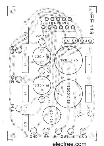
You can assemble it onto a universal PCB. It is easy. If you want a PCB layout. I am sorry. I do not have it. But you may see the components layout below. It may be guidelines for you.
Note: We adapted to increase powerful sound with…
- TDA2822 stereo amplifier
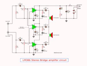
- LM386 audio amplifier with PCB
- 20 watts Integrated Amplifier using TDA2005
- Mini 40-watt audio car amplifiers using HA13001
- 12V Car Audio Amplifier circuit 50 watts output
This is PCB layout of this circuit, notice: C-220uf = C-470uF
Caution of the circuit
Of course! this circuit uses the max supply voltage of 28V. Check the power supply voltage and polarity before connecting to the circuit.
If your circuit does not work.
- Please, back to check all external wiring.
- Make sure there are no shorts.
- Then, check all the component positions.
- Also, check all solder joints.
- And make sure there are no solder bridges.
What is more? Do you high loud at the output. We have a many ways to do. But this is a good for IC. Using Bridge mode with two TDA2009 on same power supply.
Look at below
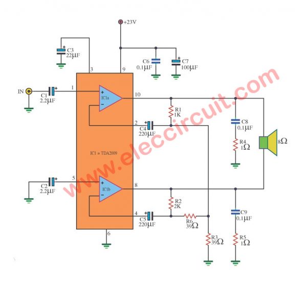
TDA2009 bridge amplifier BCL 18W
This is TDA2009 bridge amplifier circuit BCL 18W,Supply volt = 23V 2A
The TDA2009 be 10 +10W STEREO AMPLIFIER integrated circuits interesting again the one number.
We try to bring do the circuit amplifies 18W sizes better or Power Amplifier BCL 18W by IC TDA2009. This circuit character model 18W Bridge amplifier the sound better model OTL amp.
We use power supply just one group be 23V only. Make good convenient.
When use 4 ohm loudspeakers. Will give the electric power about 18watt or 20Watt.
If you want to the system stereo as a result just build enhance again the circuit. Request have fun 18W Bridge amplifier TDA2009.
Not only that. Here is a great stereo chip amplifier.Look at:
TDA2030 stereo amplifier circuit with PCB
GET UPDATE VIA EMAIL
I always try to make Electronics Learning Easy.

I love electronics. I have been learning about them through creating simple electronic circuits or small projects. And now I am also having my children do the same. Nevertheless, I hope you found the experiences we shared on this site useful and fulfilling.
Hi,
this was very useful page and i wish to assemble an amplifier with TDA2009A.
Can you please tell me from where i can purchase the PCB for this..?
is it EE149? I checked this for online but disappointed?
Is it available with the retail stores?
Please help me.
regards
jeevan
+91 9663390030
Hi,jeevan
Thanks for your feedback.
I don’t know where but the PCB.
In addition, this circuit This circuit also has the https://www.eleccircuit.com/20watt-integrated-amplifier-by-tda2005/
It’s a good amplifier for beginners in audio domain or schools student, highschool student, higher school university student, in understanding the principle of amplifiers, and then going to more complex circuit of amplifiers.
The specifications of this amplifier its not so good for an audiophile , but for a person who want a cheap amplifier its good , the ratio cost/performance its good.
hey i am basically searching for a 2.1 channel to make. so does the tda2009 process only the treble??? i am confused. please can you help me.
Tda 2009 Ata dia ki 5w +5w bajano jabe
this was vary usfull to me i made this sound amp and also iam i it its working super
Can we use 10w 8inch speker in tda2009
Hi Any one want any Pcb of any type feel free to call me ….. 09826588782
Hi any one required any type of pcb feel free to call me…. any time @09826588782
It works well but when I increase the volume on my phone, there is noise on the speaker.
Hi, this is great thing it is working very well.
I am using 5W speakers until I find 10W speakers, but can I connect on output and pair of a bass speakers, will that work and how many watts it can be when there is 5W and how many when is 10W speakers conected?
Hi ..
I want ic2009 mono PCB
am joseph i want to know how to build amprifire with tda 2009a and also i want the procedure and how to place resistors and capacitors can i get help from you
Wrong diagram
Hi,
Thanks for your feedback.
Please suggest me why it wrong diagram.
Yes, I agree it is a wrong diagram, because according to your layout R5= 1 ohm, whereas R6= 10 ohm and in the instruction below the diagram you mentioned the components we need to build that circuit: you wrote and I quote:
“IC1: TDA2009, 10 + 10W short circuit protected stereo amplifier
0.25W, tolerance: 5% Resistors
R1, R3—1.2kΩ
R2, R4—18Ω
R5, R6—1Ω”
The question is : Is the value of R5 and R6 1 ohm or 10 ohm?!
Thank you.
Yes, R5 and R6 are 1 ohm.
Will this circuit be possible to use in extra bass/bass booster ?
Yes, it’s definitely possible. Try these: https://www.eleccircuit.com/?s=bass+booster
Thanks