If you use 741 a lot, you should use 4558 dual op-amp better. It is a good choice for your circuits. Since it is like having two 741s inside a 4558, it also has a dual high-gain op-amp, a gain bandwidth of 3 MHz, a slew rate of 1 V/μs, an input offset voltage of 0.5 mV, and a dual supply of ±18 V.
Example of 4558 Dual Op-amp Circuits
For you get clear idea see example circuits list below
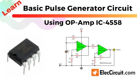
4558 dual op-amp pulse generator
This is a sample pulse generator using op-amp. We often use the 555 timer IC to build a simple pulse generator. Because it is popular, easy to buy it, and cheap.
But sometimes, we do not have them. So we use others ways or ICs probably choose this IC. Op-amp is a good choice. It easy and cheap as well.
How it works
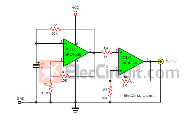
simple pulse generator using 4558 dual op amp
We can use the op-amp in many circuits. Now we will use it as an oscillator that high quality.
The pulse is a kid of square-Wave or astable multivibrator. It is the most basic oscillator. The status of signal changes all times.
What is oscillator?
Oscillators convert DCV from a power supply to ACV, pulse.
In the circuit above, it uses an op-amp(IC-1458) as the main component a few parts.
The frequency output is set by value Resistor and capacitor-C1.
The C1 capacitor to change capacitance per frequency value
- 1uF gives 8Hz
- 0.1uF gives 50Hz
- 0.01uF gives 700Hz
- 0.001uF gives 6KHz
In this testing. I use capacitor-C1 of 0.1uF.
We put the IC1b to boost up the output current and to be a buffer to load.
You can use other ICs such as RC4558, LF353 instead of IC-1458.
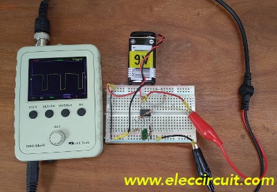
Build a Simple pulse generator using an op-amp on the breadboard.
As the video above, it shows you testing of this circuit.
First of all, I apply a 9V battery to the circuit. Then, I want to look at the output waveform, so use a small oscilloscope. It can show a square waveform.
Next, I measure that output voltage with a digital voltmeter, it can read about 3V.
After that, I measure the output frequency, it is about 50Hz.
This circuit is just a simple experiment. We have not learned the principles of it. Also, it is not suitable for practical using since the output is not steady.
Simple Function Generator using LM1458 Op-amp
This is function generator using op amp. As usual the function generator will be expensive and difficult.However, this is a simple circuit with only two ICs.
This circuit is suitable for experiments. The output is 3 waveform , Square wave signal amplitude 7Vp-p, Triangular wave = 2Vp-vp and sine wave = 2Vp-p all have the frequency 1kHz.
We use 2 x LM1458 IC number, is the main equipment this a dual op-amp IC. This circuit uses op-amp 4 section, follow circuit image.
The IC1a is square wave generator, Assumed initial, C1 is charging voltage at inverting input pin to zero, Until voltage at non inverting input voltage is slightly positive.(A ratio of the op-amp output offset voltage determined by R1 and R2)
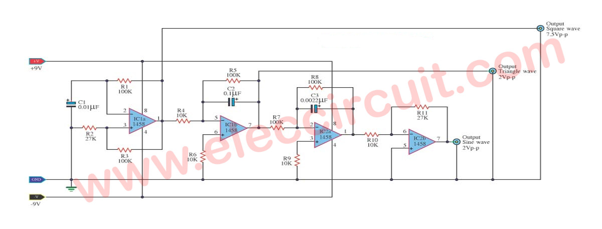
Circuit diagram of function generator using op amp
This time difference of the voltage input Enough to make the output of an op-amp in the volatility as a “high”.
When the output becomes high, C1 begins charging, the voltage at pin inverting, start over non-inverting input, an output swing to push down to zero.
which C1 Discharging again.
This is different from the first round, the amplifier output to an inverse alternating between low and high indefinitely. This produces a rectangular signal.
In the middle of the second op-amp. Defined as is integrator system, the input of the op-amp second is a square wave signal. The object of the first op-amp,.
The output of the op-amp is a triangle wave, whose amplitude is 2Vp-p only.
The triangular signal through op-amp 3, which determines the signal integrator, The output its image as a sine,.
Through to the fourth op-amp to amplify the signal to increase, with the inverting amplifier, the signal phase with the third op-amp.
This circuit use power supply: +9 V and-9V, IC number RC4558, or LF353 ICs used instead.
Buy JRC4558 Op-amp Here
GET UPDATE VIA EMAIL
I always try to make Electronics Learning Easy.

I love electronics. I have been learning about them through creating simple electronic circuits or small projects. And now I am also having my children do the same. Nevertheless, I hope you found the experiences we shared on this site useful and fulfilling.

This circuits not good
Hello hakan,
Thanks for your feedback.
I will try it again.
Se ve muy bien lo haré y luego veré los resultados