In this post, I am going to show you 3 high volt generator circuits.
Caution:
These Circuits Can Produce High Voltage. Thus they may kill you!
Efficient Flyback Driver High Volts circuit using IC555
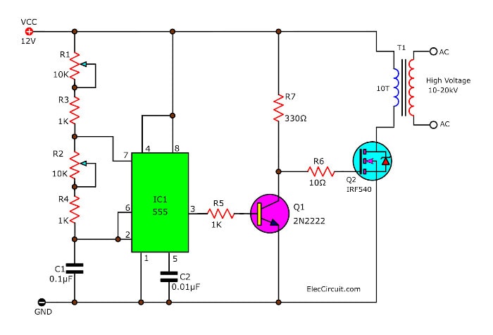
This is an Efficient flyback driver circuit, a good and fairly efficient flyback driver circuit.
All parts can be obtained easily from Radio Shack, including the MOSFET.
This circuit uses a 555 timer IC to generate a pulse. Then, a 2N2222 gets a frequency as a square wave. That is set with the capacitor and the potentiometers.

Next, The 2N2222 drives the gate of the MOSFET. And the MOSFET delivers the pulse to the 10 turns winding on the flyback.
If you build this circuit. You need to adjust the potentiometers. Until you get the highest voltage output.
The circuit will run from +12VDC to +15VDC at about 3A.
The MOSFET must be heatsinked, this is important. While it runs, it is so heated.
If the MOSFET still gets too hot or burns up. You may can add a 4 ohm (for a +12V supply) or a 5 ohms (for a +15V supply), between the source lead of the MOSFET and the primary terminal of the flyback.
Make sure that these resistors have the proper power rating for the voltage and current that they will be carried.
The flyback should be wound with ten turns of 14-16 gauge solid wire, cover with some electrical tape. Any previous primary winding should have already been removed before winding the new one.
Learn: How does NE555 timer circuit work
Simple High Voltage 120VAC to DC-900V
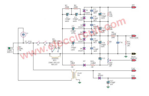
Today we come to see the simple high voltage Generator circuit ideas, that it can converter the AC line 110V or 120V to DC900-volts. In-circuit use 8 x voltage input. When see this circuit also we use technique Diode and Capacitors.
Each other model conventional. Make voltage tall can go up , for this my circuit thinks. May give current get not tall , about 50mA. But usability should be careful specially. Because of it is high voltage. The detail adds friends , please read in the circuit. Request have the amusement with High voltage spill equal DC 900V output.
High Voltage power supply 3000V
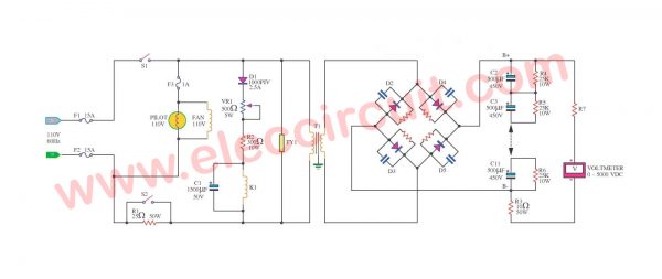
This is a high voltage power supply 3000V DC. The diode 4pcs.(D2-D5) in this circuit is a model at have to pressure electricity size turns back topmost (PIV) 1000V 8-8.25A. The resistor and capacitor the connection straddles to mourn one by that one has 470K 1W sizes and 0.01uF 1000V model ceramic respectively. The capacitor C2-C11 be supposed to a value of about 500uF and 450V durable pressure electricity minimum rates (the direct current) K1 be Relay 24V ( the direct current). At dare to touch 25A T1 sizes are a pot transforms the sky that has the coil secondary 2200V(RMS) 500mA durable electric current minimum rates. Because this circuit gives electricity tall many pressure then should use the carefulness specially and inappropriate for a novice.
GET UPDATE VIA EMAIL
I always try to make Electronics Learning Easy.
Related Posts

I love electronics. I have been learning about them through creating simple electronic circuits or small projects. And now I am also having my children do the same. Nevertheless, I hope you found the experiences we shared on this site useful and fulfilling.


Please Be CAREFUL when Constructing These Circuits!!!
If you are going for best contents like me, only pay
a visit this web page every day for the reason that it offers quality
contents, thanks
Heya i am for the primary time here. I found this board
and I find It truly useful & it helped me out a lot. I hope to
provide something back and help others such as you aided me.
I have to thank you for the efforts you have put in writing this blog.
I really hope to check out the same high-grade content by
you later on as well. In truth, your creative writing abilities has
inspired me to get my own, personal website now 😉
Oh my goodness! Awesome article dude! Thank you so much, However I am having troubles with your RSS.
I don’t know why I cannot subscribe to it. Is there anybody ellse having identical RSS problems?
Anyone that knows tthe solution will you kindly respond?
Thanx!!
You need a diode into primary to avoid destroy the transistor
hi what is the value of the cap?(.01) please answer
Hello,
why you are using 100V Mosfet? please use similar but for 800-1000V and you will see that you do not need a heatsink 🙂
can I use IRF540 on this circuit????
Why that my 555 always blow up the set up that imake is that im using 1 watt for all resistors.please advise something helpful to solve this problem.next thing is that im adding salt water capacitor a size of jam glass container with an output of more or less 30 kv to the flyback neg and poss output.this thing can possibly affect to damage. My t555 ic.please give some suggestions about this thank you.
If you add a diode backwards across the primary of the flyback it eliminates inductive voltage spikes which can potentially kill your mosfet transistor!
(I killed 5 until I added the diodes!)
can u please give me a solution for my question it is that how to produce 7amps current as an output by giving dc voltage as an input to the circuit , one important thing is that without using transformer please help me guys.
I built ic555 flyback driver but my 555ic is overhead .Why ic555 is overhead in this circuit?
Question on your Efficient flyback driver circuit. You show a P-Channel MOSFET, however the IRF510 is an N-Channel MOSFET. What is the correct interpretation?
Hello Ricardo Ferrer,
Thanks a lot. You are a good person. I just updated it.
Have a great day.
I need to generate 7.5KVDC from 24VDC input and lower current application ie less than 1mA for Air ionization application.
Please suggest me best design solution.
Hi, Shouldn’t the resistor be 330K in the first circuit? (its put as 330R coming to the collector of 2N222)?
That would essentially short circuit the power supply when BJT is ON!!!