Here is the Dual power supply circuitfor lab.
You can select voltage levels are 3V,5V,6V,9V,12,15V at 1A
and -3V,-5V,-6V,-9V,-12V,-15V at 1A.
Use LM317 (for positive volt) and LM337 (for negative volt).
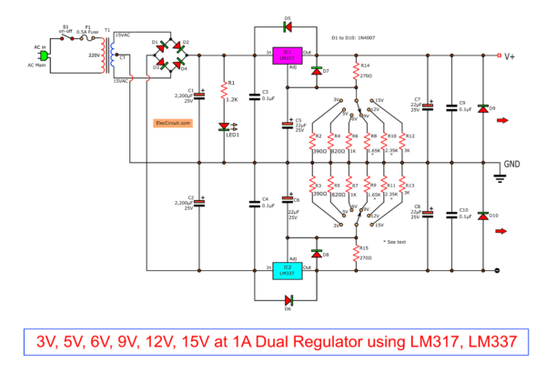
Controls Voltage Output by S2 For +Vout and S3 for -Vout.
The transformer is of 2A size. And the both IC holds heat sink.
Read detail more in a circuit.
Our friends are looking for a dual power supply positive, negative and ground for experiments various circuits.
In some times we need to have experiments about an OP-amp IC – LM741. Which must use level voltage power supply of +9 volts and -9 volts, or when we a preamplifiers circuit or tone control circuits but they use supply voltage of +15 volts and -15 volts
We think this circuit will respond to your needs certainly because…
- Can provide the positive, negative voltage at size 3, 5, 6, 9, 12 and 15 volts respectively and the current output under 1.5 amps.
- Easy to use with rotating selector switch to selects level voltage as you want. Do not have a voltmeter measure the output voltage.
It is circuits simple and cheap to make because the IC that have been popular are LM317 and LM337.
Recommended: 7805 regulator datasheet & pinout
How it works
As show figure below, here is a step-by-step oppress.
- There is the diode 1N4001 – D3 and D4 acting full-wave rectifier side the positive voltage. Then so filter waveform to smooth with a capacitor C1(2,200uF).
- Next, entered to the input of IC1(LM317T) that is a positive regulated IC, it can adjust the voltage to changing of 1.2-37 volts and provide the maximum output current of 1.5 amps.
- The output voltage can change as the value of resistor R2 and changes the resistance of R3 to R8, by selector switch S2 to choose the resistance as you want, to we have a voltage level from 3, 5, 6, 9, 12 and 15 volts.
- The capacitor C7(22uF) is determined impedance and reduce a transient on the output of IC1-LM317T.
- The capacitor C3(0.1uF) is used when we install the IC1 far from C1 too much.
- Capacitor C5(22uF) reduce the ripple signal before it is amplified when the high output voltage up.
- Capacitor C9 reduces the ripple that appears on the output.
- Both diode(1N4001) D5 and D7 for protects the IC1 from discharging of C7 and C5 when the input is shorted circuit.
- The negative section like the positive as above.
- The diode D1 and D2 are rectifier diode in a full-wave negative model, by has IC2-LM337T is the negative DC regulated IC. For all resistors and capacitors that also act as same as the positive as described above.
Recommended: LM317 Calculator
Also LM317 power supply circuits
Next ideas,if you want to other voltage in variable voltage form e.g. 4.5V,7.5V,13V, etc. You can add the VR1 in adj pin of the IC1-LM317 and IC2- LM337 look like to Best DC power supply 3Amp to adjust 1.2V-20V & 3V-6V-9V-12V
OR
0-60 volt DC variable power supply using LM317&LM337 : So well circuit, start voltage at zero voltage! and higher maximun at 60 volts.
The circuit above list may be unnecessary for you. Because large. And too expensive. see this circuits better.
LM317 Linear power supply Regulator selector 1.5V,3V,4.5V,5V,6V,9V 1.5A
My first Variable DC Power Supply 1.2V to 30V 1A by LM317 It’s easy and cheap as possible.
These circuits require enough power supply. Do you have this one? If you do not have it. Look:Learn Many Power supply circuits
GET UPDATE VIA EMAIL
I always try to make Electronics Learning Easy.
Related Posts

I love electronics. I have been learning about them through creating simple electronic circuits or small projects. And now I am also having my children do the same. Nevertheless, I hope you found the experiences we shared on this site useful and fulfilling.

Hi
thanks for offering applicable p.s circuit diagrams.
the resistors must be of a specific type? (1w, 2w, 5w, 1% …)
Hello, Dênis
The entire resistors are 0.5W 5%.
Hi, syed reza roodashty.
Thanks your comment and interesting.
This circuit do not have PCB layout.
But you can put them on Universal PCB Board.
Hi, Dênis
Thanks for your comment.
The resistors you can use 0.5 watts or 0.25 watts at 5% or 1% (0.5 watts 1% are best but does not cheaper)
thanks for posting the power supply circuit diagram
in the
Dual power supply 3V,5V,6V,9V,12,15V with LM317,LM337 circuit does the 220V apply for only over in Europe and 120V for the usa ?
Would there be anyone willing to construct the project for me if so for how much if they supply parts ?
Thank you !
Hi, I need only positive voltage. To get that IF I erase the negative regulator [Lm337 part] . and connect the GND with the ground output of bridge. Will it work ?
will not download at all
hi.!!! me i only use the 12v only..its ok if i will not put the other resistors?
Sir,Im John from the Philippines, my question is? If I only need the positive side IC1-LM317T, what arrangement or adjustment of diagram will be made for us to assure that it will work as well, can we erase or not include the lower part of the diagram?
cant you give us a 220 volts ac input voltage to 5 volts , 12 volts , 15 volts variable output dc voltage !!
How is the selector switch constructed
Hai, i would like to know the component list for 5v dual power supply…
input giving 5v dc. i want output 230v ac? give sum suggestions.
Is it possible to supply 2 separate output voltages from this particular power supply, not just 1 pos 1 neg? Regards,
Hello every body
Can someone help me
I lost my paper that contain a plan
About dual power supply
With component:
LM317, LM 377, 2N3055, MJ2955.
Thanks a lot
MOR
Hi MOR
What do you want? You want 3A variable power supply using LM317 and LM337 and MJ2955 and 2N3055