Friends interested digital voltmeter circuit very much. But cannot buy ICs since it is very ancient.
Now there is digital voltmeter panel meter that easy to use as
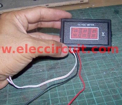
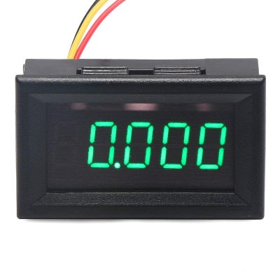
Figure 1 is 0-50V scale. Display with LED 7 segment. In cost 3$ dollar only.
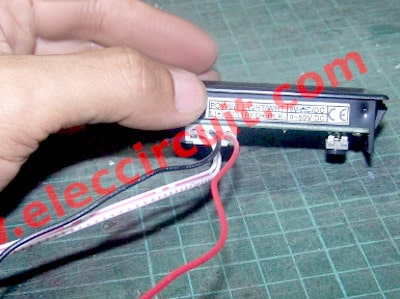
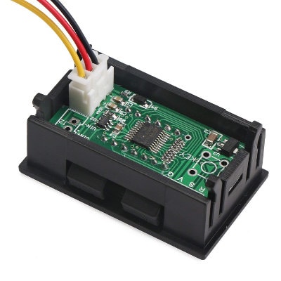
Figure 2 is wires connector or terminal by white is power supply of 9volts DC or AC and Input wires is a black as negative(-) and the next one a Red wire as positive (+). on 0-50V range full scale.
So fixed to most my working.
Therefore is need to use a power supply for it. As Figure 3 I selected old 12V DC adapter at 450mA as because I do not use it for any operation. (already for use)
But it uses 9volts we should reduce voltage down to it.
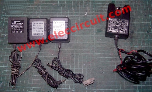
Figure 3 Many DC adapter is used as power source.
Then I open the DC adapter see obviously (Figure 4) they use LM7812 for 12 volts DC regulators
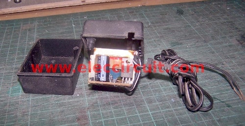
Figure 4 open inside this DC adapter
I will remove it then modify circuit as Figure 5 instead of them.
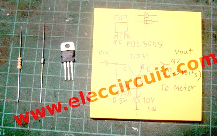
Figure 5 All parts to modify as 9-volts DC regulators. Which have one transistor MJE3055 or TIP41 or TIP31 is NPN transistor 2A 40V.
Next one is 10V Zener 1watts that is used as 10-volts steady voltage. And 470 ohms resistor to bias current to Zener and base of the transistor for high current output. Which this meter use current about lower than 100mA only.
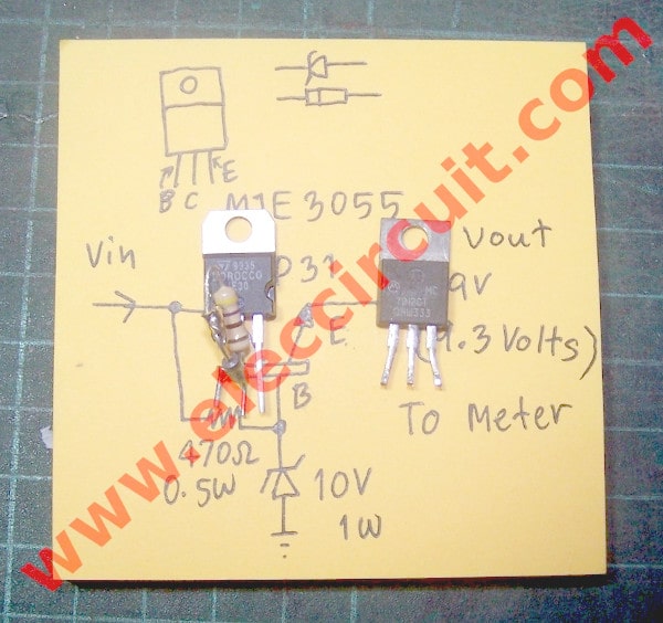
As Figure 6 The compare between the transistor regulators set is modified, which take them to replace the IC-7812.
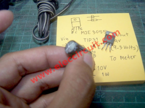
Figure 7 I found the electrolytic capacitor blob or not good for used in future. I change it with 1000uF 35V is higher voltage than old one.
Recommended: 0-50V 3A Variable Power supply Project
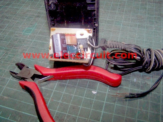
Figure 8 The 9-volts DC adapter adapted successfully.
Video: Testing, it is very accuracy. Compared with digital multimeter.
I measure a voltage of 9-volts battery results is 8.3V same them.
3 wires LED digital voltmeter panel
If we have a 3 wires LED digital voltmeter panel.
Here is its Back. We are looking at the 3 wires, red, black, yellow.
How to use it?
The wiring of 3 wires in a LED voltmeter.
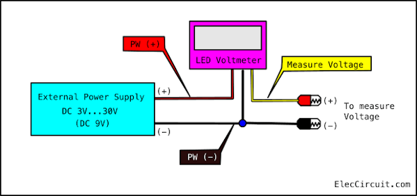
- RED, PW (+) is a positive voltage of Power Supply
- Black, PW (-) is a negative voltage of Power Supply
- Yellow, to measure a voltage
We need to use the external DC power supply to them, 3V to 30V. In this case, I use a 9V power supply and it should be a fixed regulator.
Here are a few related circuits you may find helpful, too:
- Many ideas of 12V and 5V Dual Power Supply Circuit Diagram at 3A max
- Microcontroller | Digital power supply circuit, 5V 3A using LM350 or LM323
- 1.5V to 5V boost converter circuit for microcomputer
GET UPDATE VIA EMAIL
I always try to make Electronics Learning Easy.
Related Posts

I love electronics. I have been learning about them through creating simple electronic circuits or small projects. And now I am also having my children do the same. Nevertheless, I hope you found the experiences we shared on this site useful and fulfilling.

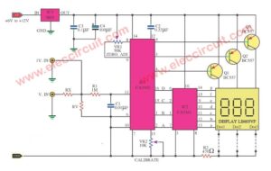
The IC Chips CA-3161(2) are Available on E/BAY.They are Expensive but still exist!!!!
Vout= Vz – Vbe(Tip 31)= 10v-.7v= 9.3v(9v3) and Vz=zener voltage
Hi, MR OHM1970
Thank a lot for your feedback.
Now I cannot buy CA3161IC.
how to i make 9v 1A dc from 9v 1A transformer?