When making a counter circuit with a 7-segment display, one of the first integrated circuits that comes to mind is the CD4026. Even though this IC is ancient, as I have been using it for more than 30 years, it still holds out very well with its ability to both count and drive a 7-segment display.
The CD4026 is pretty simple to use, has low power consumption, and is stable, plus it is compatible with TTL IC, which is why it is suitable for basic digital circuits. By itself, it can count and display one digit (0-9). However, two of them can be cascaded together to count more digits using the carry-out pin.
CD4026 Decade Counter / Divider CMOS IC
The CD4026 is a counter CMOS chip that counts up to 9 using a five-bit Johnson or Libaw-Craig code. It also has an integrated decoder to drive a 7-segment display in numerical order (0-9).
Furthermore, multiple CD4026s could be cascaded together to get more than one digit on the 7-segment displays. Because it is both a counter and a 7-segment display driver, it is often used in compact or low-component devices.
Features
Here are a few of the many interesting and valuable features of CD4026:
- It contains both a counter and a 7-segment decoder/driver.
- It can effortlessly interface with many types of 7-segment displays.
- Ideal for driving low-power 7-segment displays directly
- Maximum supply voltage 15v
- Max current per output 15mA
- Maximum speed of operation 5MHz
- It can interface with timers, microcontrollers, or TTL.
- It can be cascaded together to display more digits.
- Tested for quiescent current at 20V
- It has 16 pins and is available in PDIP, GDIP, and PDSO packages.
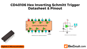
- Schmitt-triggered inputs.
Pinout
Next, we have the position of its legs or pinouts. What does each pin do? Otherwise, you may apply the wrong voltage and damage it. Or why doesn’t it work? Because we misconnected its pins.
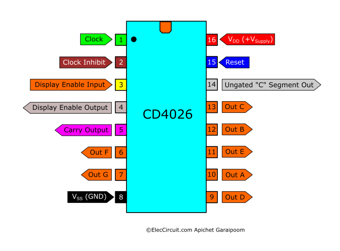
CD4026 Decade Counter /Divider CMOS Pinouts
| Pins | Initials | Names | Descriptions |
|---|---|---|---|
| 1 | CLK | Clock Input | Count up by 1 when the “high” clock pulse is applied. |
| 2 | CI | Clock Inhibit | Connects to the ground or “low” to enable clock input; disable clock input when connected to “high.” |
| 3 | DEI | Display Enable Input | Enable output to the 7-segment display when connected to “high.” |
| 4 | DEO | Display Enable Output | Always output a “high”; it enables other IC’s 7-segment display when cascaded. |
| 5 | CO | Carry Output | When the IC counts up to nine, it outputs a “high” clock pulse to ICs in a cascade that counts higher digits; also, a divide-by-10 output. |
| 6 | F | Out F | Decoded output for connection with a 7-segment display. |
| 7 | G | Out G | Decoded output for connection with a 7-segment display. |
| 8 | VSS | Ground Supply | Connects to the ground or “low” of the circuit. |
| 9 | D | Out D | Decoded output for connection with a 7-segment display. |
| 10 | A | Out A | Decoded output for connection with a 7-segment display. |
| 11 | E | Out E | Decoded output for connection with a 7-segment display. |
| 12 | B | Out B | Decoded output for connection with a 7-segment display. |
| 13 | C | Out C | Decoded output for connection with a 7-segment display. |
| 14 | UCS | Ungated “C” Segment | Outputs “low” when the count reaches 2; otherwise, stays “high.” It is used when performing division functions. |
| 15 | RES | Reset | Reset the count to zero upon receiving a “high” clock pulse. |
| 16 | VDD | Voltage Supply | Connects to the voltage supply or “high” of the circuit. |
Specifications
- DC Voltage Supply (VDD) Range: -0.5V to +20V
- Input Current: ±10mA
- Max current per output 15mA
- Power Dissipation: 500mW at -55°C to +100°C
- Operating Temperature Range: -55°C to +125°C
- Maximum Clock Frequency: 6Mhz
- Symmetrical Output Characteristics
Applications
- Decade counting and driving 7-segment decimal display.
- Frequency division.
- Counting up to very high digit when cascading.
- Clocks, watches, timers.
- 7-segment display driver in meter applications.
Equivalents for CD4026
If you cannot find the equivalents for this IC, then try using the ones that have similar functions as listed below.
- CD4033
- CD4511
- MC14511
CD4026 Datasheets
The CD4026 is not a complicated chip; in fact, it is very simple to use. However, if you need the specific details surrounding this chip, check out the manufacturer’s datasheet below.
- CD4026B by Texas Instruments
Example Circuits
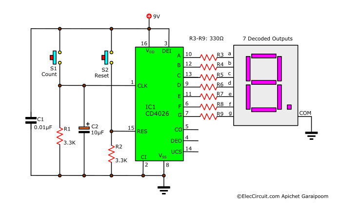
CD4026 Basic Single Digit Counter Circuit
First, let’s look at this basic single-digit counter circuit using the CD4026 to learn the basics of using the CD4026. It counts up by one when pressing the S1; upon reaching nine, it will loop back to zero. Additionally, it resets the count to zero when the S2 is pressed.
How it Works
First, we need to supply the power to the circuit and the chip. The positive supply goes to pin 16, and the ground goes to pin 8. Technically, the supply voltage can be from 3V to 8V; however, we recommend using from 5V to 12V. In this case, we are using a 9V battery.
Secondly, we connect the outputs A, B, C, D, E, F, and G of IC1 to the corresponding inputs of the common cathode 7-segment LED display. Additionally, we should add current-limiting resistors (R3 to R9) because when each of the outputs is “high,” the voltage goes up to almost 9V. Even if the current is very low, it still is not ideal for both the IC1 and LEDs.
Thirdly, we connect pin 15 to the “low” of the circuit, or in other words, the ground. When we press S2, the current will flow through it down to R2, causing pin 15 to be “high,” triggering the reset function of the CD4026.
Next, we connect pin 2—which is the Clock Inhibit (CI)—to the ground to enable clock input into IC1. Likewise, we connect pin 3—Display Enable Input (DEI)—to the “high” of the circuit to enable the output A-G for the 7-segment display.
Lastly, we have to input a “high” clock signal to pin 1 for IC1 to start counting. To achieve that, we are using S1, R1, and C1. When we press the switch S1, the current flows, causing the state of pin 1 to be “high,” whereas R1 and C1 are there to provide a basic debounce for the switch, i.e., preventing double-input when only pressing once.
Whereas other output pins—5, 4, and 14—are left unused, these pins will become important later when cascading multiple CD4026s together.
Automatic 0-9 Counter Circuit using CD4026 and NE555
We also try replacing the switch with an NE555 astable multivibrator oscillator to generate a clock pulse for the CD4026. The NE555 generates a clock at the frequency of 1Hz, or one clock per second, meaning that the circuit above automatically counts from 0 to 9 and then back to 0 again at one-second intervals.
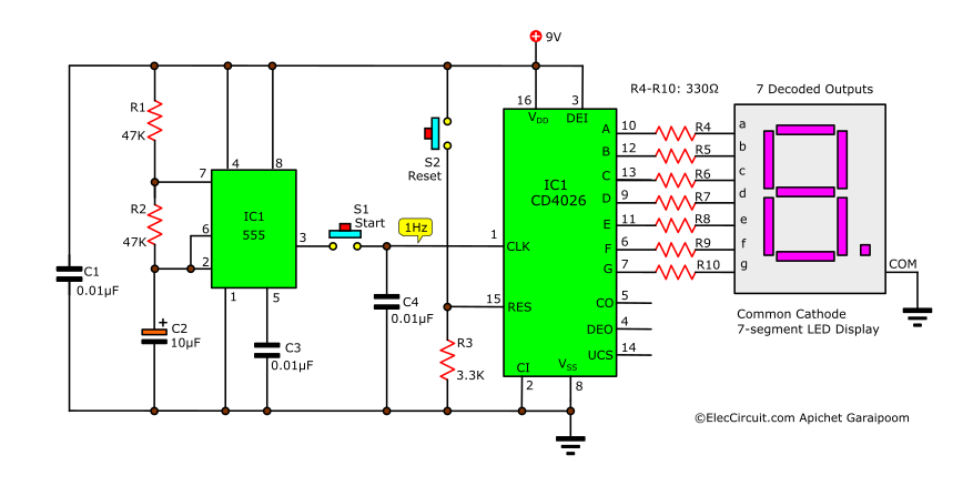
Additionally, we can change the resistance of R1 and R2 to increase or decrease the frequency of the oscillator. For instance, to get 3.3Hz, or about three seconds, we can just replace both R1 and R2 with a 15K resistor.
Side note, this circuit can easily be modified into an electronic 0-9 die machine, or random number generator, by changing the resistance of R1 and R2 for a higher frequency.
Two Digit Counter Circuit using CD4026
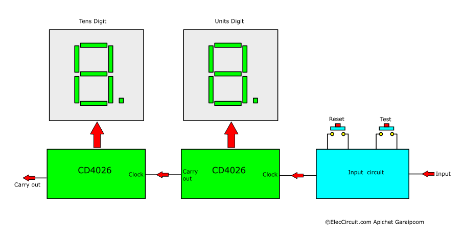
This is a digital counter circuit using the CD4026 with dual 7-segment displays. It is a two-digit counter that counts to 99 on the 7-segment displays. Furthermore, this circuit also has a reset function, and it can be used for many different scenarios, for instance, counting items, counting people, and more.
How it Works
As mentioned earlier, the CD4026 can drive a 7-segment display directly. In this usage, there are two CD4026s cascaded together, where IC1 counts and displays the ones digit and IC2 counts and displays the tens digit; both ICs work on the rising-edge clock.
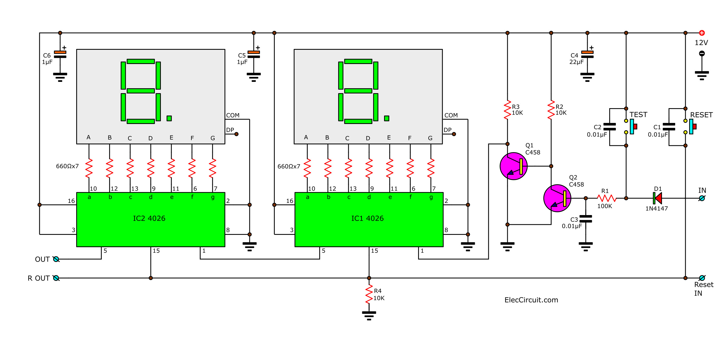
The input clock is connected to pin 1 of IC1, and then we connect pin 5—which is the Carry Output (CO)—of IC1 to pin 1 of IC2. This means that IC2 will receive a clock when the IC1 count passes nine. We connect pin 15—Reset (RES)—of both ICs together so that we can reset both ICs to zero simultaneously.
Since the counter circuit is pretty sensitive and is prone to double-counting errors, we would need to add a transistor circuit to function as a sort of buffer. The transistor circuit allows a “high” clock into IC1 whenever the input voltage is 2V or higher.
Initially, the input voltage flows into the circuit via D1 and R1 to B of Q2, biasing Q2. Then, Q2 conducts the current from R2 to ground, leaving no bias current for Q1. As a result, Q1 stops conducting current, and the “high” clock flows through R3 to IC1’s pin 1.
After IC1 receives the first clock pulse, it will count up to “1” and display it on the 7-segment display. As more clock pulses come into the circuit, IC1 counts up by one for each individual clock. Upon IC1 receiving the tenth pulse, it will loop back to 0 on the display and send a single clock pulse from pin 5.
This single clock pulse from IC1 is sent directly to pin 1 of IC2, causing it to count up by one. At this point, the display shows the number “10,” representing the tenth clock pulse the circuit receives. When another clock pulse comes into the circuit, the IC1 counts up to one, and the display now shows “11.”
This process repeats again when the total number of clock pulses approaches 20. At the twentieth pulse, IC1 loops back to “0,” and IC2 counts up to “2.” The number displayed on the 7-segment display is the total number of clock pulses the circuit received, “20.”
Eventually, at the hundredth pulse, both ICs loop back to “0,” and the IC2 sends a single clock pulse through pin 5 for the hypothetical next IC that counts the hundredth digit. Therefore, to expand the amount of digits this circuit counts, we simply need to cascade more CD4026s.
Want more brilliant ideas? Here’s how to get them through electronic circuits.
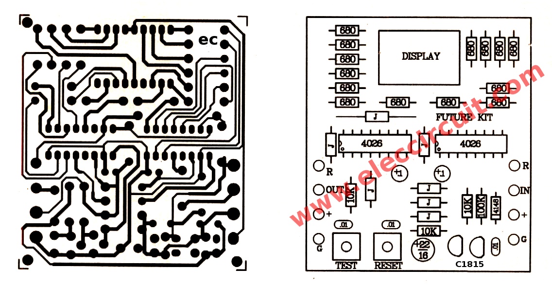
Building this Circuit
Here are the PCB and component layout of this circuit.
Testing and Application
After finishing building the circuit, apply the 6-12V power supply to the circuit using either batteries or a power adapter.
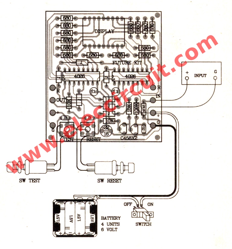
The 7-segment display should display “00.” If it does not, then press the reset switch to reset it. Now try pressing the test switch multiple times; the number on the display should correspond to the number of presses. Lastly, press the reset switch to return to the beginning. Now that this circuit is fully operational, we can connect its input to a door sensor, IR sensor, clock generator, or a simple switch.
Conclusion
The CD4026 is an excellent choice for a simple single-digit counter and a 7-segment display driver in a single chip. In addition, we could cascade multiple CD4026s together to count higher digits with ease. However, for more advanced counters, such as those that count more than three digits or reversible counters for timers, we would need to look for different chips.
Check out these related articles, too:
- Random counter circuit with 7 segment display
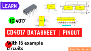
- IC 4017/CD4017 Datasheet | Pinout | 15 example
- Digital counter circuit using CD4510 & CD4543
GET UPDATE VIA EMAIL
I always try to make Electronics Learning Easy.
Related Posts

I love electronics. I have been learning about them through creating simple electronic circuits or small projects. And now I am also having my children do the same. Nevertheless, I hope you found the experiences we shared on this site useful and fulfilling.
how so that the circuit can be used up and down counter (for score board).
Hola señores que tenga un feliz día
Me gusta la pagina muchos los proyectos me gustaría los proyectos con pics microcontraladores de la micro chip.
Gracias Oscar.
Hi, can you movie the counter up or down? Like increase the number and go back if you want to decrease the number?
I can’t find IC CD4026 . Is there any possible IC I can use? Instead of CD 4026.
Hi friend
Can you tell me what type of segment can i use? Common cathode or Anode?
The BZ 505 type work with circuit?
Thanks
Andreas
i have a 10 pin dual 7 segment display can i use this circuit with this kind of display or do i need an 18 pin dual 7 segment display
Hi,I check your new stuff named “2 Digit Simple digital counter circuit using CD4026” regularly.Your story-telling style is witty, keep doing what you’re doing! And you can look our website about proxy server list.
Hello ca we change the switch as a photodiode? Thank you
Hi,
Yes, You can test it. You may change some components like R1.
Have a good day. Fun with Digital learning.
Hello laxmikant patel,
Thanks for your visit. I am happy that you are interested in this circuit.
My English is quite poor. Do you mean reset to Zero when turning on?
You may add 1uF to the beginning of C1. It acts like a reset switch on. This will reset the system to zero.
If you test it. There are anythings results. Please share again.
Thanks
Apichet
I want to make the circuits to have a memory features so that even after turning the circuits off and on the set digits must not change to zero it remain fix unless if I reset it by my self.
ic 4026 4diigit pcb 10 pis want cost calll 8217891651
Thank you for your interest in this circuit. but i’m sorry because we don’t have PCB 🙂