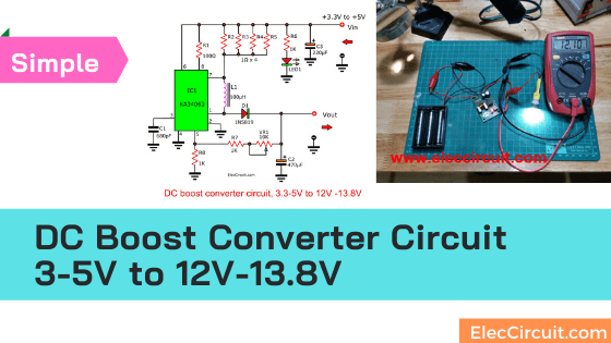
This 3V to 12V boost converter circuit turns 3.3V, 3.7V, and 4V DCV into 12V at a maximum current of 100mA. It is a type of switching power supply, and the MC34063 is its main component.
Suppose we need to use a 12V LED, but we only have 3V batteries. Since it is impossible to decrease the size of a 12V LED, it is much better to increase the battery’s voltage instead. So we should give this 3V to 12V boost converter circuit a try.
This 5V to 12V boost converter circuit is better compared to the previous circuit. For instance, it can take lower input voltage, has a higher efficiency, and has an adjustable output voltage. I have this cheap and super bright 12V LED light Bulb as seen below.
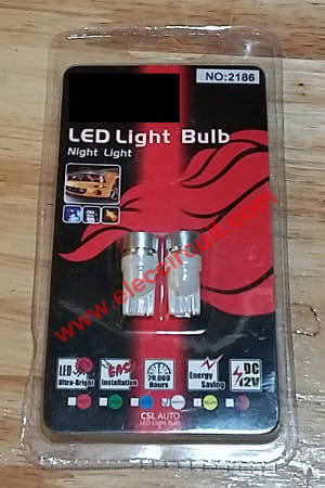
Before we can use this LED, we need to know its current. To do that, we would need an ammeter that connects in series between the LED and the power supply, as shown in both images below.
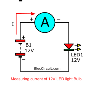
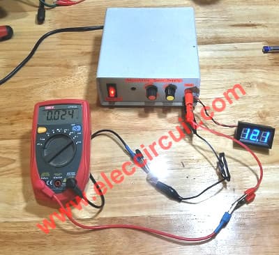
The ammeter reads a current of 0.024A or 24mA, meaning that this LED consumes only a small amount of power, about 0.2W. We calculate this wattage using the following formula.
P = V x I
12V x 0.024A = 0.228 watts
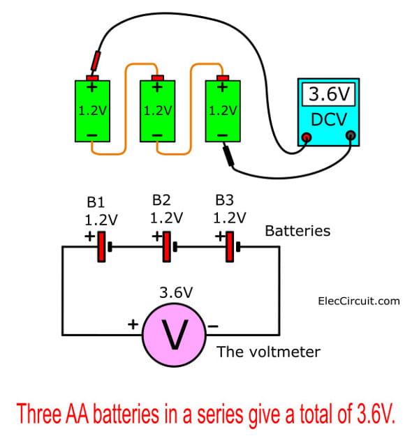
Now, let’s look at the battery. A single NiMH AA battery has only 1.2V; however, if we connect three of them in series, we could increase their voltage to 3.6VDC. Even so, we still cannot power a 12V LED with it.
How to Increase the Voltage
To increase the voltage, we need a DC boost converter circuit to convert 3.6V, 3.7V, or 4V input to 12V output.
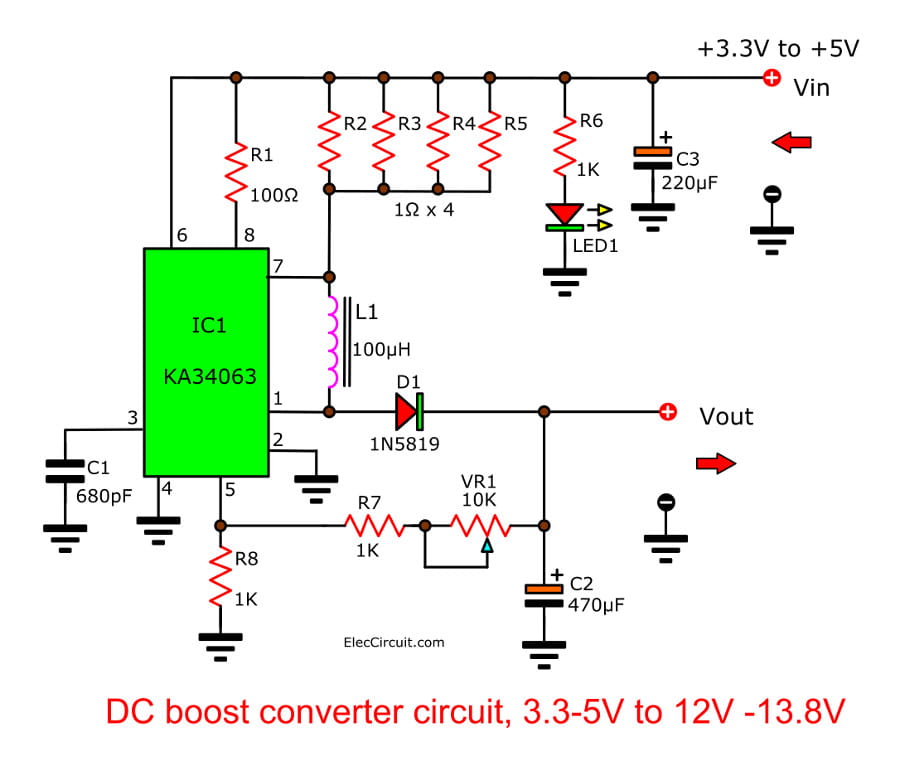
Here are some notable features of this particular boost converter circuit.
- An input voltage range of 3V to 5V.
- An output voltage range of 11V to 15V depends on the input and adjustment.
- A maximum output current of 100 mA.
- A normal switching frequency of about 43 kHz.
- Adjustable output voltage.
- Power on the LED light.
For example, if we apply an input of 3V at a current of 660mA, the output will be 12V DC at a current of 50mA. Whereas, if we apply an input of 5V at 0.3A, the output will be 12V DC at a maximum of 0.1A.
How It Works
When we connect the power supply to the circuit, it begins to operate. The IC1 functions as a step-up voltage converter. The increased voltage is outputted from the IC’s pin 1 and flows through D1 to the circuit’s output. We can adjust the output voltage further using VR1.
Assembling the Circuit
We bought this 3V to 15V boost converter circuit as a project kit that came with a PCB board. This makes building this circuit much easier. However, you can still buy all the components listed below and then assemble it yourself either on a perforated board or a universal board.
Testing and Using
In the video below, we try using the 3.6V battery to power a 12V LED again, except now with the 3V to 12V boost converter circuit.
On the PCB; He connects the power line 4, the terminal of the circuit.
As Figure 6: Testing This DC-step-up-converter citcuit using KA34063
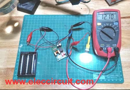
Here are the step-by-step processes of how we test this circuit.
- Connect the 3.6V battery—or 3.7V Li-ion battery—to the input.
- Connect the LED to the output and measure the LED voltage.
- Adjust the VR-10K until the voltage reading is 12V
- Measure current of the LED to be 24mA at 12V
- Measure current of the circuit to be 100mA at 3.9V
From the testing, we see that the input power is 0.39W (0.1A × 3.9V), whereas the output power is 0.3W (0.025A × 12V). Also, this shows that this 3V to 12V boost converter circuit indeed converts a lower voltage input into a higher output.
Application
- The input connects to a DC power supply with a voltage of 3.3V, 3.7V, 4.5V, or up to 5V.
- The output is used as a DC power supply for any loads. This output voltage changes by an input voltage level and VR1.
Parts List
Resistors 0.25W
R1: 100Ω brown-black-brown-gold
R6-R8: 1K brown-black-red-gold
R2-R5: 1Ω brown-black-gold-gold
Trimmer Potentiometer
VR1: 10K
Ceramic Capacitor
C1: 680pF 50V
Electrolytic Capacitors
C2: 470μF 16V
C3: 220μF 25V
Semiconductor
D1: 1N5819, 1A, 40V Schottky rectifier Diode
IC1: KA34063 or MC34063, 1.5-A Peak Boost/Buck/Inverting Switching Regulators
Buy MC34063
If you cannot find the 1N5819 40V 1A Schottky rectifier diode, you might be able to substitute it with a 1N4007 instead. However, it will not work as fast as the 1N5819, which is better at switching.
You can read more about this topic here: 1N5819 rectifier replaces with 1N4007 rectifier??
Related Circuits

I want to make solar panel mobile battery charger.I have 3watt solar panel.how will I know its voltage?
Sir,
I am most impressed with all your circuits especially teaching your son really this is so GOOD.
I want to build a project of your and need to buy n IC KA34063 I am not familiar with this IC also WHER C|AN I BUY THIS Please.
Your reply would be sincerely appreciated.
Thank you for your projects.
Regards,
Chris
New Zealand.
Cool circuit. What is the value of that COIL ?
hello, I printed the page to test the diagram. but the coil rating/value was not there… could you please mention the value of the coil . thanks in advance.
what is the value of the coil ?
Hello what is the value of coil? thanks
Kindly tell something about inductor you used and of what value and how do you made it.
Thank You
What is the value of that COIL ?
Hello
Do you have an instagram page?
Assuming I have a 12 volt in and I want 12v out – a UPS, but I want a lot of capacity
What is the downside of connecting everything in parallel and have a BMS manage the 12v in, to charge the 3 – 8 18650 batteries in parallel and then have a buck-boost converter to take the 3-volt battery bank of 3 – 8 batteries and boost it to 12v.
In other words, to get 17Ah of 18650 @ 3.7V is a hell of a lot cheaper than to get 17Ah @ 11.1V
I want to understand what the immediate red flags would be to use 3.7V instead of 11.1V for the battery configuration?
Sir,how many turns or number to generate 100uh
Hello Kolly,
Thanks for your visit. Please look at:https://www.eleccircuit.com/how-to-apply-an-inductor-from-the-compact-fluorescent-light-bulb-burned-out/
You may be done.
Thanks
The 1N4000 series diode isn’t as slow as I once thought, it’s rated speed is 1500 NS (1.5uS) to 2000 NS (2uS)
Thanks Clair Morrill.
Your experience is interesting, but the 1N4007 is less responsive to high frequencies than the 1N5819.