Sometimes, these circuits do not work. We can use the meter to check other devices. But the crystal will do not know how good or bad with the normal meter. You need a crystal tester circuit.
It is an important point. The Crystal is expensive and may long time to buy new. If we buy it too many, it is not worth. Because we seldom to use it.
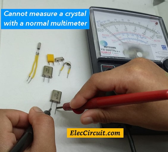
So we better create a crystal tester circuit. It can check the crystal, good or bad, from 100KHz to 900MHz. It is easy to make and low cost.
We use the crystal to generate a radio frequency, a clock signal controller. We often use it on digital circuits of a computer system and quartz watches.
Because this crystal determines the accuracy frequency. The specific frequencies such as 5.7143MHz, 3.597MHz, 2MHz, etc.
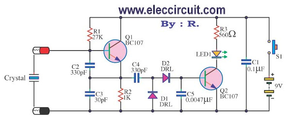
Beginning, we look at works first, in the circuit above.
The transistor Q1 (BC107) is the key to the oscillated circuit. It will generate a frequency when we put on the crystal the socket to the base pin (B) of Q1.
Then, press a switch-S1 to the circuit. The current from the battery (B1-9 volt) flows into the circuit, the oscillated signal from emitter pin (E) of Q1 pass through to C4.
The oscillator signal will be changing all the time. It needs to smooth with D1 and D2.
Then, the signal via through to C5, which helps smooth up. There is a voltage across C5, is a positive voltage to trigger a bias current to the Q2 works. So it makes LED1 light up.
The R3 limits the current through the LED1 in safety value, not exceeding 20mA. If more than this, LED lights too and short-lived to LED1.
The above principle, you will see that LED1 is illuminated, when the transistor Q1 works. The Q1 will work and build the frequency. It requires the quality crystal. With this principle, we can easily measure the crystal.
How to build Crystal tester circuit
This project use equipment less. So it can be soldered onto the perforated board, easy to save money and time.
When creating a Crystal tester circuit is complete. It is the test circuit. First, get a good crystal to test in the circuit. Then press S1 to see the LED1 brightness.
But if it goes out showing. The circuit may be wrong. You may have forgotten the battery or alternating polarity LED1 or other.
The parts of circuit
Q1, Q2: BC107, NPN transistor
D1,D2: DRL=1N4148 75V 150mA Diodes
R1: 27K 0.25W Resistor
R2: 1K, 0.25W Resistor
R3: 560 ohms, 0.25W Resistor
C1: 0.1uF 50V Polyester Capacitor
C2,C4: 330pF 50V Polyester Capacitor
C5: 0.0047uF 63V Polyester Capacitor
LED1: any color as you like.
Finally, we have the electronics tool this one on our desk. It can be used to check the crystal in radio transmitters, radio control, the digital computer clock circuit and so on.
NOTE:
This circuit does not have PCB layout. Thus, you can see the crystal tester circuit below with PCB layout. It is a similar structure of the circuit. But the detail of components slightly different. Hope you can build this project even easier.
Crystal tester circuit with PCB
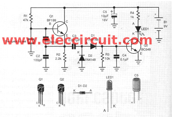
Figure 2 the crystal tester circuit using BF199 and BC548 same circuit above.
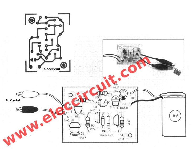
Figure 3 The PCB layout and The components layout of the Crytal tester projects.
GET UPDATE VIA EMAIL
I always try to make Electronics Learning Easy.
Related Posts

I love electronics. I have been learning about them through creating simple electronic circuits or small projects. And now I am also having my children do the same. Nevertheless, I hope you found the experiences we shared on this site useful and fulfilling.

Can this circuit work with 5V voltage? Any modification needed? Thanks.
Yes, it should work from a 5v supply w/o modification.
Is it used to test the crystal remote control of the cooler??
Hello. Do you have a crystal checker circuit that will connect to a separate ordinary frequency counter?