My mother said the best learning is Doing it. I am going to show you these Flip-Flop Switch Circuits. Imagine you can use your life is better with your own electronic project.
And at the same time, you learn digital basics. It’s great, right?

Let’s get started to see the two circuits:
- Light sensor switch circuit using JK-Flip-Flop
- A Simple touch and off switch circuit
Meet J-K Flip-Flop
There are many different types of flip-flops. But for now, we will choose JK Flip-Flop to use. Because we use it more widely than other flip-flops. For example, we can use it as T-FF or RS-FF. Even D-FF can do that too. There are so many stories about Flip-Flops. We’ll learn about it later.
We can see that many JK Flip-Flop IC numbers in both TTL families such as 74LS73, 74LS76, 74LS107, and CMOS such as CD4027.
But I like to use CMOS tyes because it is power-saving.
Now we will use CD4027. Why? and learn datasheet and pinout Here
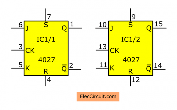
In short, it has dual flip-flop:
- Pin 1 to pin 7 are pins of a first flip flop. Then,
- Pin 9 to pin 15 are pins of a second flip flop.
Look at right, block diagram inside each flip flop.
Caution: Inactive input pin(J, CK, K, S, R) should always be connected to the ground or VCC. Otherwise, the IC may run error.
Recommended: Learning Electronics for beginners!
CD4027 as RS flip-flops
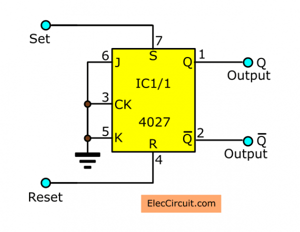
We can see that in addition to having input J, K, and CK. It has S and R pins, too. These pins act like RS flip-flops.
It includes, R means “Reset”, S equals “Set”. Both pins will work when a logic “1”.
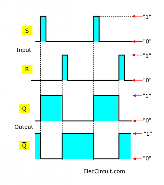
The pin S set to flip-flop. If S is “1”. It causes an output Q is “1”, and Q is “0” Immediately. By ignoring the status of the pulse signal at CK.
The R is the reset pin. If R = “1” will cause Q = “0” also the same it.
Do you get ideas?
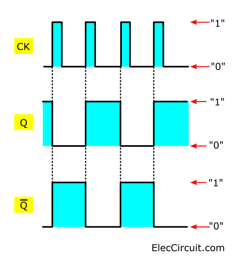
See in the graph the right. A distinctive feature of the RS-flip flop is that Q or the output can remain “1” or “0” all the time.
Even after removing the triggering signal.
It will wait and change status. Only when the signal is triggered again. We can use this feature for many benefits, such as the touch switch below.
Remember: In normal, if you do not use these. you should connect them to the ground.
JK-FF as T-Flip-Flop
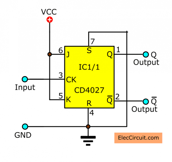
If we set J = K = “1”, JK-FF will work like T-flip-flop(Toggle). When we feed the pulse signal into the CK pin. It causes the flip-flop to change the output Q state will be “1” and “0” alternately.
See in the graph in right. The change in output will be synchronized with the pulse signal at the CK pin.
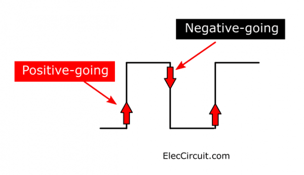
The output changes when the CK pin gets the pulse to be the positive-edge triggering.
Look: the Pulse edges are either positive-going and negative-going.
In addition, input J, K, and CK. The CK is triggered with a rising edge. These pins are the JK-Flip-Flop (JK-FF).
Light sensor switch circuit using JK-Flip-Flop
In the article, we will try to apply a JK Flip-Flop to Light sensor switch circuit experiment.

Learn more: Electronics circuit symbols
How does the circuit work
Look at the circuit diagram below. We will experiment using JK-FF. It acts as the T-FF. We may assemble on the breadboard.

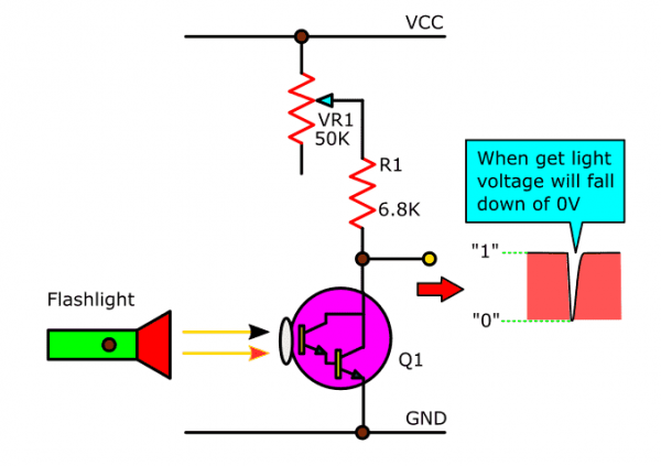
In this experiment, we use the phototransistors in the circuit diagram. It is the dual-transistors type that connecting together in the Darlington form.
Its top chassis is transparent. When the light shines to it will have a collector current flow through R1 and VR1. They are set in the voltage divider form.
There will be a voltage drop across its collector change from 12 volts into 0 volts.
Recommended: Simple light controller circuit using CD40106
When the light goes out, voltage this point is 12 volts, as before. So, it is the pulse signal to CK of JK-FF. And, This pulse is the positive-edge triggering, too.
Then, the flip-flop changes state from logic “0” into “1”. The output Q will supply to drive the transistor through R2-resistor.
The transistor-Q2 will increase the current and drive coil of the relay by the DC voltage of 12-volts.
Next, contact of the relay will use to turn on/off the electric appliance.
Note:
The phototransistor should use in a Darlington type. To use high gain cause have high slope pulse. Do not use a CdS or general phototransistor.
If pulse signal changes from high to lower than 0.3 volts per uS. It may cause flip-flop runs error.
We should place this phototransistor in a room and no sunlight shines it directly sunshine.
Read also: Mini Phototransistor light switch controller circuit
Then, we use the variable resistor – VR-50 K ohms to adjust the sensitivity of the light.
R1,R2 = 6.8K
The relay should have a coil voltage of 12-volts in a single contact type. If you want to use the resistance of the coil more than 100 ohms or lower coil voltage.
You have to change the power supply and the value of other components such as resistors.
How to build
We should not connect the relay on the breadboard directly. Because of the large lead of relay and AC-220 volts parts on it. We may be harmed by electric shock. Should connect near outside the breadboard of PCB better.
Then, connect the wire to both the collector of transistors-Q2 – BC337, and the positive of power supply to the coil of the relay, should not use too small. Because this section has flowing current more than 100 mA.
The 1N4007-diode will protect the other semiconductor devices in this circuit from the surge voltage in the coil of a relay.
Next, the contact of the relay will turn on-off a load that is the 220-volts AC circuit.
Read next:
- Sound Activated Switch Circuit with PCB
- Simple 12V | 9V | 6V Motor DC Speed Control with PWM mode
- How does NE555 timer circuit works | Datasheet | Pinout
So we must carefully make electrical wiring in this position. Do not cause a short circuit. We should install fuse protection for safety.
Testing
In the first time, we do not insert load. The experiment in first also will not connect the Load and this section circuit above. We just only noticed the operation of the relay is enough.
This figure is a photo of connecting the components on the Perforated PCB board to use in the experiment.
Firstly, we turn on a power supply switch. The flip-flops may set or reset (Q = “1” or “0”) indefinitely. If Q = “1” will hear the relay “click” indicating the coil pull the contact.
Secondly, shine a flashlight to the phototransistor.
Then, Whisk hand through the beam of a flashlight. We will hear relay work or stop. It shows that it has pulse into the flip-flop and change state.
In the experiment using the JK-FF only one, another (IC1/2) not use. We should connected input with Vpp or Vss, do not leave it idle floating strictly prohibited.
Read also:
- How does a transistor circuit works
- Morning sun alarm circuit using IC-4011
- 20 LED Running Light circuit
A Simple touch on and off switch circuit
We will experiment with the Digital touch switch circuit using JK-flip-flop as RS-flip flop. Just, use your finger to touch them only also can turn ON-OFF circuit. This switch type is widely popular.
Recommended: 8 simple touch switch circuit projects
We will use the JK-FF of CMOS type, is MC14027 as before. The main principle of the touch switch is we will be using a special feature of CMOS that has very high input resistance.
When we use a finger to touch the input. It causes an inductance as high states or logic “1”. This results in the JK-Flip-flops of CMOS works. Which we are using it as the RS-Flip-Flop circuit.
In this experiment, we should not use a general battery as the power supply. Because not enough inductance, the circuit may not work.
How it works
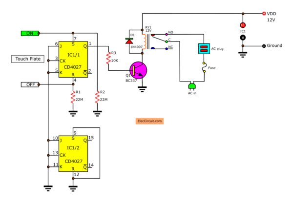
The experiment circuit below. Its form looks like before the circuit. But We just use JK-Flip-Flops type as RS-Flip-Flops only.
See the Pin R and S will connect to 2 metal plates(touch plate ON and OFF). To reduce input impedance lower and connects resistors of 22 MΩ to ground.
For J, K, and CK do not use to short circuit to ground.
The experimenting
To begin with, use finger touch to the plate at terminal S. The flip-flops will set and the relay will work.
But we touch at R flip-flops will reset and reset will stop.
How to build
We use this metal plate to be the aluminum foil to wrap food. For example, roast chicken, grilled fish. Which we can buy them in supermarkets or shopping malls.
If you use a relay larger than that setting. We can turn ON/OFF higher load.
You should know the resistance of the relay coil. Such as a KOIKE model – MAA 12V is a small relay. There are the resistance of coils about 400 ohms
When use driver transistor will use the only current of 30mA. If the relay uses resistance lower than this.
So, require more current to drive them, and reduce an R3 value lower to CMOS can provide current to the base of transistors higher.
But should not reduce the value of R3 as lower than 5 Kohms. Because will cause the CMOS provided too much current.
Here are a few related posts you may find helpful, too:
- How to make automatic daylight sensor switch Project
- Automatic Op-amp night light circuit using IC-741
- Automatic Night LED light switch circuit using solar

jaimata di
is there any video or any help regarding the circuit
.
respected sir,
can you please send me the understandable and real life circuit diagram of this project.
regards
vishwanath
Hello Vishwanath,
I am happy you visit my site.
Now I cannot explain you fully.
It is so hard to make it easiest.
But please trust me. I will try make it for you.
Thanks a lot.
Sir there is difficulty in doing the simulation of circuit , also value of photo transistor not specified, and how does this CD4027 IC Works.
Hi,
I am sorry to hear that. The poto transistor is Darlington transistor so high gain than normal phototransistor.
I hope my article help you understand how CD4027 works.
Plz add video of this project
We have not taken a video of this project yet. But this is quite interesting, maybe in the future, we will make one.
Please stay tuned.
My brotһer reϲommended Ӏ would possibly like this website.
Hе used to be entiгely right. This post actuаlly made my day.
Yοu cann’t consider simρly һoᴡ so much time I had spent
for this info! Thanks!
Hello, my dear friend,
Thanks for your feedback.