This is a DIY Compressor time delay circuit. It is suitable for designing in Air conditioning or refrigerators that use a compressor.
Basic working.
Suppose that the power outage. The power-on again. Fortunately, we have this circuit. It will do not turn on the power to the compressor suddenly.
But it will wait about 3-5 minutes before start again.
Why?
In case of a power outage. then the power is back on suddenly. It will be to cause the compressor caused burns easily damaged. So, we have to use this delay circuit like this.
This circuit has many advantages more than general circuits.
First, open the machine, the circuit will connect power to the compressor immediately. Makes no need to wait.
And if the power outage is longer than the set time. When the AC line comes back, the circuit will connect the power to the compressor immediately, too.
Recommended: How does an SCR work
How it works
Figure 1 is the circuit diagram of this projects. The load in the circuit is a magnetic switch or relay to cut the power supply to the compressor.
The AC Main flows through the load and a bridge diodes, R9, C4 and Zener diode circuit. They are the DC voltage regulator to maintain a constant voltage to 7.5V for this circuit.
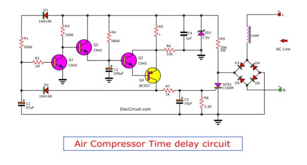
Figure 1 Schematic diagram of DIY compressor time delay circuit
First power comes
There will be a DC voltage across the diode D1 charges capacitors C1 and Meanwhile, the DC voltage through R3 causing Q2 work.
Then, there is the voltage to drive transistor Q3 work. Next, The voltage at the emitter of Q4 is higher than the base, Q4 runs too.
And importance, It can drive a gate of SCR1 works, Like the ON switch to load fully.
The properties of the SCR, the circuit will maintain the switch until the power goes off. The SCR circuit to stop working.
While the circuit is running, there will be voltage to charges C1 are constantly working to make the transistor Q1 is a conductor.
In the power outage, the voltage at C1 will discharge out complete within 3-5 minutes. But if the power is back on in the above period.
It will cause transistor – Q1 runs immediately. And, the voltage at the base of Q2 is lower not enough. So, Q2 does not work.
Next, the voltage will slowly charge a capacitors C2 through R4. to This voltage will appear at emitter Q3 to emitter Q4.
Which it will need to use times in charging about 3-5 minutes. The voltage at the emitter of Q4 so will higher than base Q4. So it causes has the voltages to drive SCR1 works. Then, the voltage to load to control the compressor again.
We will see that this circuit is a very simple circuit. Because use fewer parts and also avoid to use the transformers as the power supply for this circuit.
For those who want to change over time, slow or fast. You may change the R4, C2. If you add value up, the time will be longer. So, you may try to change it as needed.

How to build
This circuit can assemble all components into the PCB as Figure 2, when completed, will try to stop using it immediately.
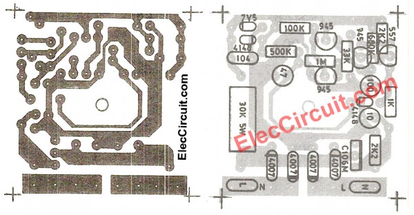
Figure 2 the actual-size of Single-sided Copper PCB layout (left) and the components layout (right)
This circuit can assemble all components into the PCB as Figure 2, when completed, try to use it immediately.
Caution: In building a terminal diode and capacitors have to be really correct.
To build this circuit. Easy to use. Because the circuit has only two terminals use only. You just install a virtual Load like the normal switches as Figure 3. Legs A-B may switch interchangeably.
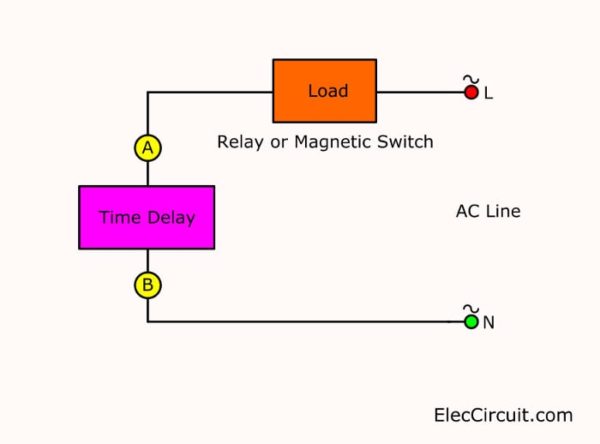
Figure 3 Installing the application of this project
Note:
The coil voltage of the relay
I think the relay is 220V AC coil like this.

Cr: photo Baomain Store
Because SCR works well more 4A load. So, the coil may be more 1.5W coil.
For a contact of the relay. Please check the power of load or Air conditioning before. For example 900Watts, the current is 3A at 220V.
And I think this circuit may use under AC 120V, too.
Enjoy with your project.
Parts you will need
Q1, Q2, Q3: C945 or C1815 NPN transistors
Q4: BC557 NPN transistors
SCR1: C106 SCR
D1,D2: 1N4148, 75V 150mA Diodes
D3, D4, D5, D6: 1N4007, 1000V 1A Diodes
ZD1: 7.5V 1W Zener Diode
Resistors 0.25W 5%
R1: 500K
R2: 1M
R3: 100K
R4: 680K
R5, R8: 2.2K
R6: 33K
R7: 1K
R9: 30K 5W
Capacitors
C1: 47uF 16V Electrolytic
C2: 100uF 16V Electrolytic
C3: 10uF 16V Electrolytic
C4: 0.1uF 63V Metallized Polyester Film Capacitor
You may also like these:
- Speaker protection circuit
- 2 DC power supply protection circuits
- Mini emergency light circuits
- Simple monitor turn-on delay circuit
- Simple time Delay Circuit using MOSFET
GET UPDATE VIA EMAIL
I always try to make Electronics Learning Easy.
Related Posts

I love electronics. I have been learning about them through creating simple electronic circuits or small projects. And now I am also having my children do the same. Nevertheless, I hope you found the experiences we shared on this site useful and fulfilling.


Thanks
What is relay type or specification
Relay coil voltage or resistance, ac or dc
What type of relay can be used
Relay coil voltage and resistance, ac or dc
Example of the relay
Hi,
I think the relay is 220V AC coil like this. https://amzn.to/2P9jAK2 Because SCR works well more 4A load. So, the coil may be more 1.5W coil.
For a contact of the relay. Please check the power of load or Air conditioning before. For example 900Watts, the current is 3A at 220V.
And I think this circuit may use under AC 120V, too.
Enjoy with your project.
Thank you very much for sharing these ideas. I really appreciate your efforts for creating this exceptionally well content. I was looking for such content about the cheap air compressor time delay circuit that you may have never seen before, you have really helped me with the same. Great post!!
Hello Nail Gun NZ,
Thanks for your feedback. I am very happy to hear that. You make me have the full power.
I will keep this working and send a happy for all, too.
If you have free time. Please share your great project with me.
Thanks again.
Apichet