Do you like to learn electronics with playing lighting? Yes! I also love. My collection has a lot of light sensor alarm circuit.
Or some called Light Sensitive Sound Generator circuit.
It is suitable for studying the performance of optical sensors is LDR.
They use LDR as a light sensor. It is so easy to learn for beginner or Kids. Let’s play Electronics with a light sensor, LDR. Using transistors, 555 timer, and 741 Op-amp.
Are you a beginner? Learn Basic Electronics
There are 8 circuits ideas below.
1. Light sensitivity Metronome using transistors
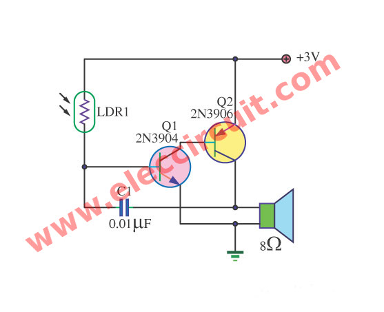
This is a Simple light sensitivity Metronome circuit.
It uses the transistor 2N3904 and 2N3906 as frequency circuit. By the sound frequency from a loudspeaker will be high and low.
When taking a flashlight to near LDR within a darkroom. It causes a resistance value of LDR is down.
On the other hands, when LDR receives the light. The resistance value of LDR is higher. And it will increase the frequency of origin sound.
We will hear frequency change continuously is like the wood keeps strokes the music there.
See More detail in the circuit.
The Schematic diagram of light sensitivity Metronome
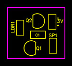
The component layout PCB
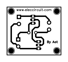
The Actual size of Single sided Copper PCB layout
2. Light Sensitive Buzzer circuit using transistor
See in the circuit a buzzer will emit when becoming dark because of Light-sensitive works. The important components in the circuit are a transistor, 2N2926, and AC128. And the light sensor is LDR or we called light-dependent resistor.
When no the light makes Q1 stop work. The Q2 and Q3 work together. Then, send current give buzzer emits a loud buzz immediately.
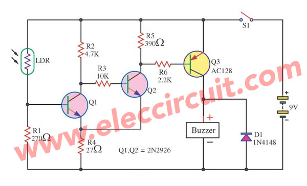
By circuit arrangement of Q1, Q2 be the character of Schmitt trigger. They help to modify the analog signal to digital 2 levels, well. And help decrease the condition disturbs too.
The detail is other, see in the circuit.
Learn How to use LM386 audio amplifier
3. Active Light Control using LDR and transistors
See in the circuit. The LED or light bulbs will light up automatically when no light or become dark.
We need to use a small lamp less than 3V only. Because this circuit uses a 3V power supply.
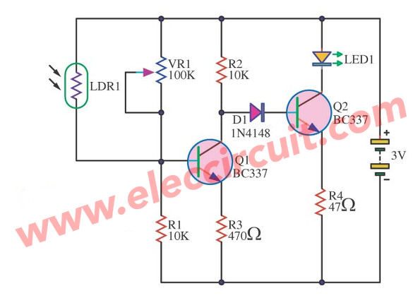
The work of the circuit
First, when there is a light affects LDR1. It will have resistance at LDR1.
It causes Q1 work. And there is a voltage across C lead of Q1 and Ground just a little. It has low bias current cannot make Q2 runs.
See D1 in serial with B of Q2, This makes a voltage at C of Q1 compared with the ground. Its voltage needs to be about 1.4V so will make Q2 work.
But when LDR1 no the light. It causes more resistance until no current flows through B of Q1. This makes Q1 does not work.
Then, have current flow through R1, D1 get in bias B of Q2 works. And It causes LED1 is bright up.
Also, see VR1 in parallel connection with LDR1. We adjust it to set a sensitive light of LDR1.
4. Opto-Tone (Control sound by light)
The Opto-Tone (Control sound by light) circuit with IC 555 and sensitive light by LDR.

5. Simple 555 light detector
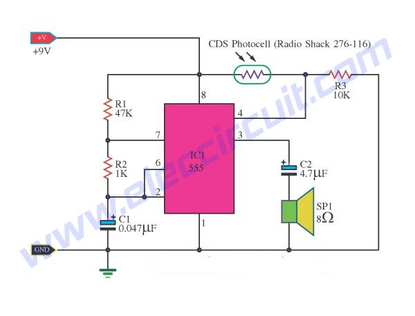
This is an idea for a light detection circuit. We use the 555 timer IC. Usually, we used to produce frequency (astable multivibrator) a lot easier.
The single IC with a few resistors and capacitors, adjust value them to control the frequency output. It can drive speakers directly like the buzzer sounds.
The CDS or LDR is a resistor to change its value by lighting. When we apply pin 4 (reset pin). If be hight voltage this circuit works.
LDR and R3 together are a simple voltage divider circuit.
When the light is very low resistance of CDS. Then, the voltage at pin 4 is high. We will hear the tone of the sound.
6. Light Dark Detector Alarm using 555
See the light detector alarm circuit. Like above we use LDR is a light sensor. And use 555 timer for what read here.
This our circuit uses the integrated circuit 555 as main again. You can choose many different numbers such as LM555, NE555. Event use LM7555 CMOS version(use low energy) all right.
555 is tone generator.
Use pin 4 (reset pin) if it is high will turn on 555 work well. But others hand, It is low voltage. It will stop 555 work.
Connect LDR to pin 4. So, we control voltage to turn on-off 555 or tone by LDR and selecting of S1.
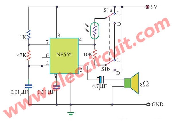
There 2 options to detect the light.
The Light and Dark by choosing of S1.
Light Mode
We press S1 in an L (lighting) position.
And there is the light shines at LDR (Photoresistor). The circuit will emit buzz out of a loudspeaker.
Dark mode
When we press S1 in a dark position and no light at LDR. It will no sound on loudspeaker too.
This easy good circuit for friends. You will have fun with this 555 light detector circuit.
7. Tone Generator Control with light using 555
This is a tone Generator circuit that interesting. Because of can control the sound by light. By using the integrated circuit NE555 as main again.
It produces a frequency sound in Astable Multivibrator model or pulse generator circuit.
And use 25-ohm small-sized loudspeaker to emit sound.
For the equipment detects the light.
We use an LDR. Because of usable good easy and economize with.
For the tone of sound can change by C1. If you use large capacitance will be low tone sound. But when low capacitance is high-frequency sound.
See more detail in the circuit.
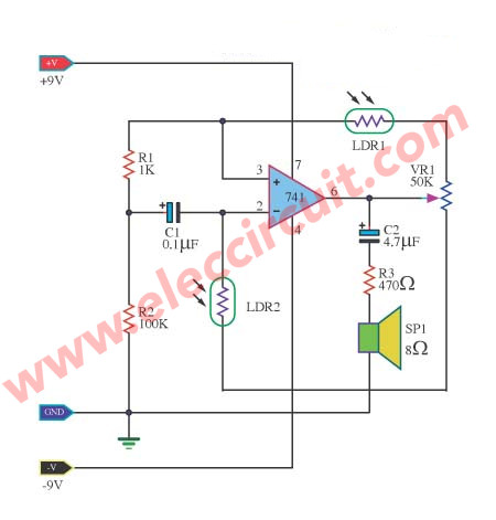
8. Audible Light Sensor using IC-741
This is audible light sensor circuit. It uses 741 op-amps as based.
And use LDR is a light sensor again.
We know 741 is good at the signal amplifier circuit. But we also can use them as a pulse oscillator generator. And output to a small speaker.
The VR1 has value 50k to control the sensitivity of the light sensor.
Use a small size of the speaker only. Because output has a low current.
GET UPDATE VIA EMAIL
I always try to make Electronics Learning Easy.
Related Posts

I love electronics. I have been learning about them through creating simple electronic circuits or small projects. And now I am also having my children do the same. Nevertheless, I hope you found the experiences we shared on this site useful and fulfilling.




iam very excited.i have just started to work with light alarms.
Really very excited…..
I am very happy by this mini project.
its a good help for those who want to learn and build electronics projects. thanks and more power to you.
Do you sell any of these projects as a kit?
Hello Robert Furman,
Thanks for your visit. I am happy that you want to build these circuits.
But I am sorry that tell you. No, I cannot sell these projects for you. I am very busy.
However, I believe in you. You can build these on the universal PCB.
Although difficult to begin. But you can definitely do it. Trust me, it can be done quickly, too.
And I will wait for your progress. Please do not forget to share with us.