Imagine we want to detect the frequency. But we will use what methods or equipment is appropriate. Choose NE567 is Better. Why?
The NE/SE567 tone and frequency decoder is a highly stable
phase-locked loop with synchronous AM lock detection and power
output circuit.
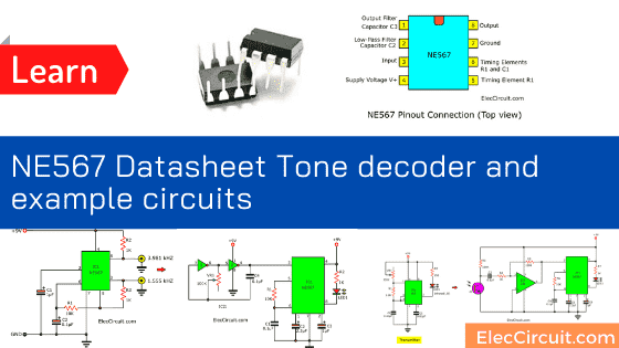
NE567 is good at driving a load whenever the input frequency within its detection band.
We can set the bandwidth center frequency and output delay freely by helping from four external components.
If you still not get ideas. Please keep reading and see example circuits. You may make you a little smile.
NE567 Datasheet
The NE567 has typical looks like NE555 with the 8-DIP pattern. Look at illustration is Pin connections.
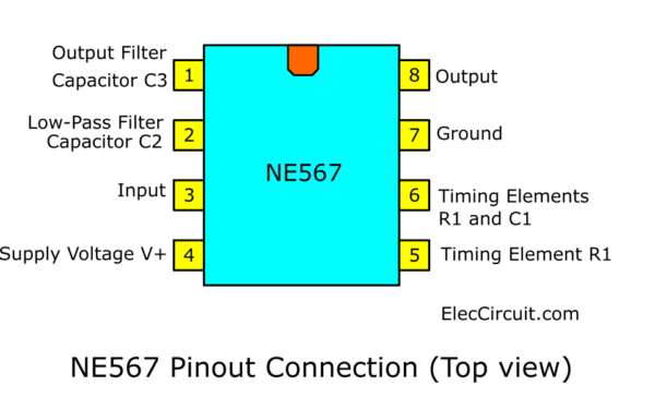
The NE567 has typical looks like NE555 with the 8-DIP pattern. Look at illustration is Pin connections.
What is more? Read the features of NE567 below.
Features
- The wide frequency range of 0.01Hz to 500kHz.
- High stability of center frequency
- Independently controllable bandwidth (up to 14%)
- High out-band signal and noise rejection
- Logic-compatible output with 100mA current-sinking capability
- Inherent immunity to false signals
- Frequency adjustment over a 20-to-1 range with an external resistor
- Military processing available
APPLICATIONS
- Touch-Tone decoding
- Carrier current remote controls
- Ultrasonic controls (remote TV, etc.)
- Communications paging
- Frequency monitoring and control
- Wireless intercom
- Precision oscillator
Block Diagram
Of course, The NE567 reduced the number of electronic devices, reduced a lot. It makes us work easier, more automatic up. But understanding it Inevitably becomes more difficult as well. The block diagram may be a part to help us understand how it works. See below.
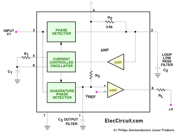
We will see the main internal structure. And basic external devices
Recommended: Learning electronics for beginners
ABSOLUTE MAXIMUM RATINGS
- Operating temperature
- NE567 0 to +70 °C
- SE567 -55 to +125 °C
- VCC (Operating voltage): 10 V
- V+ (Positive voltage at input): 0.5 +VS V
- V- (Negative voltage at input): -10 VDC
- VOUT (Output voltage (collector of output transistor): 15 VDC
- TSTG (Storage temperature range): -65 to +150 °C
- PD (Power dissipation): 300 mW
Description
In short, the NE567 tone decoder is วงจร phase-locked loop. We can set it easily as follow.
- Pin 8 will be “low” when the input frequency matches the frequency within the IC (fo).
- This frequency-fo is from R and C (calculated from 1.1 / RC). The value of R is between 2K to 20K.
- We may use NE567 to detect low frequencies of 0.01Hz and up to 500KHz. (Use with low frequencies Should allow time to lock together for 1 second or more.)
- The value of the C-low pass filter should use n / fo. We might define n from 1300 to 62000. The output capacitor used is 2 times.
Recommended: Transistor Crystal Oscillator circuit ideas
Example NE567 Circuits
It’s my fault. If you do not understand the operation of it My English. Like a child learning to walk. But some said that Explanation is not important. If I propose a circuit that is good enough. They understood it.ฺ
Basic tone detector circuit
This circuit is small for learning the tone detector works. We set the frequency-fo is 1.1kHz approximately.
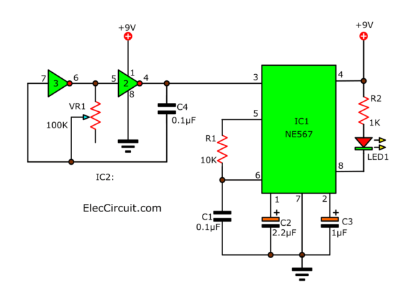
IC2 is CD4049—the Hex inverting buffer/converter or not gate. Adjust VR1 to control the frequency at 1.1kHZ tone.
Read next: 4049 Hex inverter Datasheet – Square wave oscillator
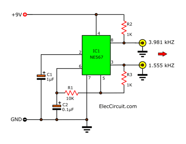
Oscillator generator twin frequencies circuit
Usually, we used the IC – NE567 is only a tone decoder circuit. But friends believe or not.
We bring it to a frequency generator circuits as well. The output has twin frequencies, 1.555kHz and 3.981kHz.
- Both on the square waveform signal
- It has a level amplitude in voltage output maximum as same as the power supply.
How to change frequency
This defines the frequency of the Resistors and the Capacitors. We calculated from 1.1 / RC. The R is normally set of 2K – 20K.
You may test it on the breadboard before. I hope you have fun with this circuit.
Electronic circuits parts
R1: 10K 0.25W Resistors
R2,R3: 1K 0.25W Resistors
C2: 0.1uF 63V Polyester Capacitor
C1: 1uF 25V Electrolytic Capacitors
IC1: NE567 Tone decoder/phase-locked loop
B1: 9V power supply
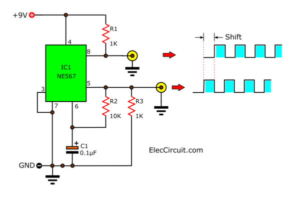
2-Phase Oscillator using NE567
Infrared Remote Control System
Look at the circuit below. This is a simple infrared control circuit. But it works quite well. Adjust VR1 until LED1 in the receiver circuit lights up.
It’s easy, but how do we understand how it works?
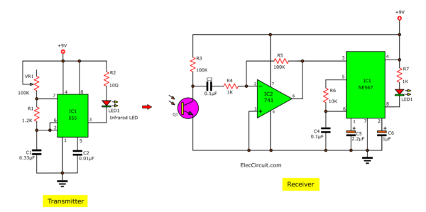
I want to explain it to you more understand easily.
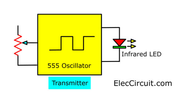
Transmitter
The transmitter uses 555 timers as the main parts. It can produce a square waveform frequency to drive the LED infrared.
The Receiver
There are the 3 main parts inside. The phototransistor gets infrared light for the transmitter. It will transform the light to the AC signal.
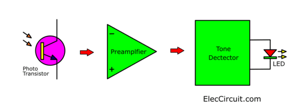
Then, the 741 op-amps as the preamplifier to increase to the higher signal. Next, The NE567 detects the frequency of that setting, approximately 1.1kHz.
Read also: 2 CH Infrared Remote control using NE567
Here are a few related posts you might want to read:
- Learn 741 op-amp circuits basic with example
- Infrared Intruder Alarm circuit diagram
- IR – infrared receiver circuit
GET UPDATE VIA EMAIL
I always try to make Electronics Learning Easy.
Related Posts

I love electronics. I have been learning about them through creating simple electronic circuits or small projects. And now I am also having my children do the same. Nevertheless, I hope you found the experiences we shared on this site useful and fulfilling.

What Can I Say??? Old Chip..Great Little Circuit!!( Low Parts Count Too!!
Hi Mr.OHM,
Thanks for your feedback my friend.
According to the datasheet, max voltage for LM 567 is 9V!!! DO NOT POWER IT WITH 12V!
Hi Adrian,
Thanks for your helping. You are correct.
Thanks for the explanation but how can I find this component NE567 in my Proteus simulation software