Here is a simple 5-20 minutes timer circuit using the 555 timer integrated circuit. This circuit uses a buzzer alarm and has a choice of 5, 10, 15, or 20 minutes for the timer. It is also very uncomplicated and compact.
In addition, we can modify this circuit to control other loads apart from the buzzer because the 555 timer has a maximum output current of 200mA. If you want to learn more about the 555 timer, consider seeing our article on it here: How does NE555 timer circuit works.
Simple 5 Minutes Timer Circuit
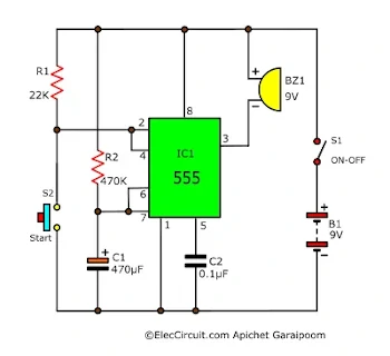
Let’s start with a simple 5 minutes timer circuit first. We power this circuit with a 9V battery and use the switch S1 to turn it on and off. The main component is the 555 timer IC, which operates in a monostable, or timer, mode.
The switch S2 functions as a start button for the timer. The timer starts when we press S2, and when it reaches 5 minutes, the IC555 will sound the buzzer. The timer duration depends on the value of R2 and C1. To calculate the time, we will have to use this formula: T = 1.1 RC.
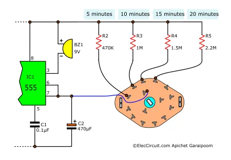
Now that we know how this timer circuit works, let’s look at the 5-20 minutes timer circuit that has 5, 10, 15, and 20 minutes timer options.
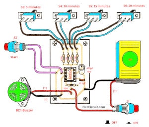
5-20 Minutes Timer Circuit
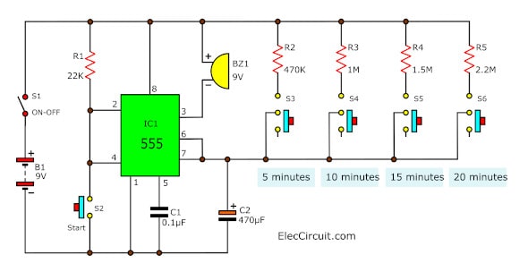
This 5-20 minutes timer circuit is set up in a way that we could easily choose which resistor to use while leaving the capacitor C2 the same. In other words, each of the timer durations is determined by C2 together with R2, R3, R4, or R5. Thus, the higher the resistance, the longer the duration; for instance, switching on S5 will use R4 as the resistor, thus setting the timer duration to 15 minutes. For the rest, it goes:
- Switching on S3 uses R2, resulting in a 5-minute timer.
- Switching on S4 uses R3, resulting in a 10-minute timer.
- Switching on S5 uses R4, resulting in a 15-minute timer.
- Switching on S6 uses R5, resulting in a 20-minute timer.
This circuit relies heavily on the monostable multivibrator function of the 555 timer. Monostable means that the IC switches to an unstable state when it receives a pulse and stays in that state for a set period before switching back to the original state. The duration of the unstable state is determined by the resistors and the capacitor mentioned above.
However, the timer duration may differ from the calculation because of factors such as component degradation and temperature. From our experiences, the actual timer can be up to 20% off from the calculation. We thus recommend trying the circuit first. See if it is precise enough; if not, then change the value of the resistors up or down accordingly.
Building this Circuit
Building this circuit is very easy, but first, we have to start by preparing the components we would need, the list of which is down below.
Parts List
IC1: NE555 timer IC
C1: 0.1µF 50V, Ceramic Capacitors
C2: 470µF 16V, Electrolytic Capacitors
R1: 22K, 0.25W Resistors, tolerance: 5%
BZ1: 9V Piezo sounder (incorporating 3KHz oscillator)
S1: the ON-OFF SPST Switch
S2: Normally open push-button Switch
S3 to S6: small SPST Slider Switch
B1: 9V batteries
Wires, Socket IC, etc.
Then, you could choose to assemble the circuit on a PCB as shown below.
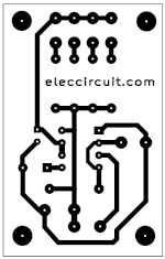
The copper PCB layout
Components layout
However, if you want to save time and money, you could also assemble it on a perforated PCB. But you would have to be extra careful, as components such as the 555 timer, electrolytic capacitor, and buzzer do have polarity.
As you can see below, we test this 5-20 minutes timer circuit on a breadboard, and it works very well.
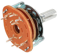
Sidenote on the switches: In the circuit above, we used four different sliding switches, but you could also use a single rotary switch, as seen below.
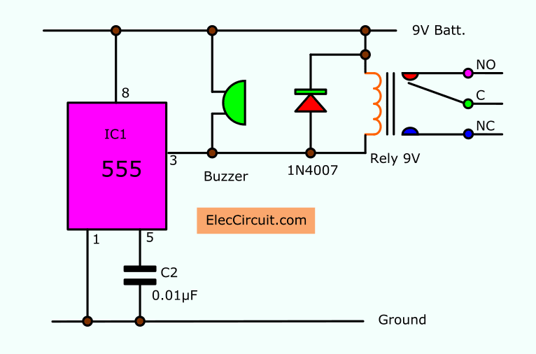
Adding a Relay for Controlling a Bigger Load
If you want to control larger loads, simply modify the circuit by adding a relay, as shown below. Now you will be able to control any load your relay allows for.
Conclusion
This 5-20 minutes timer circuit is a pretty simple yet functional project to make. It requires few components, is easy to assemble, and is precise enough to be used on a daily basis. Furthermore, the addition of a relay to the circuit allows for greater load flexibility. Nevertheless, there are alternatives out there that have higher precision, such as crystal- or microcontroller-based solutions, and we hope we can get to them in the future.
…
Download This
All full-size images of this post are in this Ebook: Elec Circuit vol. 2 below. Please support me. 🙂
Check out these related circuits, too:
- The simple long duration timer circuit
- CD4060 Timer Circuit 22 seconds to 4 hours
- Simple 555 countdown timer circuit with alarm
GET UPDATE VIA EMAIL
I always try to make Electronics Learning Easy.

You Could Use A 4 Position 1 Pole Rotary Switch Instead Of 4 Switches..It would Work!!!!
Dear Admin,
I want to make a timer circuit similar to what you shown here. But I want to connect the timer circuit to my Air Conditioner which is of 1647 Watt.
And I want to make it work for infinite loop, i.e. it switch on for 30 mins then switch off and then again switch on and so on. Please suggest me the required modification.
i did a combination of 555 and cd4047 ic
Hell Char,
Good idea. You made IC555 and CD4047 together. Please share me.
May I ask how you calculate the value of the R and C based on the wanted time?
Tnx i really enjoyed de 5mins to 30mins timer.may God bless u
Hi, dp
Thanks for your feedback.
You can normal SPST switch.
wow the timer alarm works
Hi,bee.
I am very very happy that hear you.
Please show projects to us. Your project is best!
Hello again! the problem was with my switch S2,i used a SPST instead of a push switch. Now I’ve fixed it and the circuit works!! Thanks!
admin
please help me out,how should i construct 10minutes timer
i want to turn off my pump after 15 min after i switch on please suggest a modification
hi sir please help me to make power supply 12v which ONtime is 15min and OFF for 30min and repeate this please mail imformation on my id [email protected]
I want a circuit which can switch on a 500watt load for 10 min and then switch off the same load for 10 min and switching on and off goes repeatedly. Thank you
I want to make a timer circuit for my home use submersible pump. Plz help me to make a circuit by which the pump switch offs automatically after 20mins of switch on.
What kind of buzzer do I need (voltage) ?
If I want to use a small round 5v buzzer, what do I need to change ?
Thanks.
Hi sir,i want to turn off my pump after 15 min after i switch on
i want to stop my water pump (without water related circuits) ofter 08min. please tell me
Sir,
Do you supply kits also
Hello Bhatia,
Thank you that you are interested this circuit.
I am sorry. I cannot sell a KIT for you.
But you can use other way to do with bread board. It is easy too.
When there is any progress Please let me know here.
hello! may i see the breadboard please?
Hello dcas,
Thanks for your visit. Do you want a component layout on the breadboard?
It is easy, you can do it.