This circuit is an automatic reverse polarity switch. If we apply DC voltage to any electronic circuits in the wrong polarity.
It can be caused by too much current. You must waste time to reverse the new terminal. If your circuit is important, let’s build this project to your life will better.

Automatic Reverse polarity switch using Relay
How it works
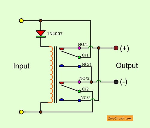
In Figure 1. We apply the DC voltage to input in the correct polarity. Secondly, the forward current flow through a diode to the relay’s coil. Then, the relay pulls in the positive voltage input from the lead C/1 flow to lead NO/1 that is the output. In a negative way from leg C/2 will through to leg NO/2 to the negative output.

Circuit diagram of Automatic Reverse polarity switch using Relay
But if we apply DC voltage wrong polarity, the diode is getting the reverse bias so the current cannot flow to the relay’s coil, the relay doesn’t work. It causes the positive voltage from lead C/2 flow through to lead NC/2 that is the output. And the negative way will flow through lead C/1 to NC/1 as negative output.
How to builds.
This circuit is very simple, so doesn’t need to use any PCB, but you can also use the universal PCB. Then put them in a small box or in the importance circuit.
The parts you need.
RY1_Relay 2 contact.
D1_Diode 1N4001 or 1N4007
Note
Pedro Hermosilla said:
Sometimes I tried the solution explained by William. They are NOT a current loss. Just a little power loss, depending on Intensity passing across
diodes ((0,6 – 0,7 V)x I x 2) where I in the current passing, 2 are two diodes conducting at the same time, and 0,6 – 0,7 is the voltage drop in a Si diode conducting forward.
For very small loads, we can try Ge diodes, (like OA95) where de voltage drop is around 0,2 – 0,3 Volts, but we are limited by the If (Forward current) of these kinds of diodes.
Thanks for sharing.
What is more?
Sometimes, use relay hard to do. Look at simple circuit below.
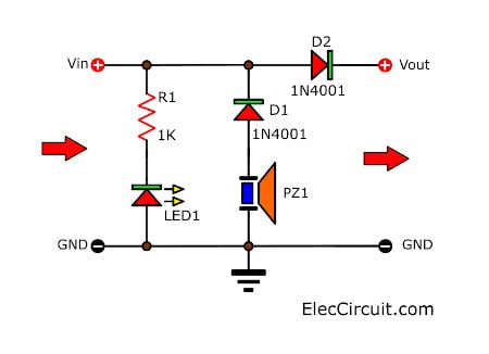
Simple Reverse Polarity alarm circuit
This is a Simple Reverse Polarity alarm by Sound(buzzer) and Light(LED display). To use such circuits. If you have identified the polarity of the power supply or power supply connector on the wafer is not clear.
The wrong polarity can cause damage and range. But when using this circuit with an active circuit, it can protect and show a correct polarity.

Operation of the circuit is not complicated. When the supply terminals to make LED1 and D1 bias direct. It makes LED1 light, and The piezo speaker PZ1 emit noise.
The lamp LED1, it would be R1, assist current limiting and voltage. To prevent LED1, no damage. But if the supply polarity is LED1, D1 will actuate bias. D1 does not bias the LED1 not lit.
And piezo speaker PZ1 not emit noise. The D2 works, The D2 works, because of it is direct bias. Make a power supply circuit as usual
Build reverse polarity alarm
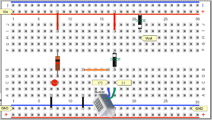
This circuit is easy you can use a universal PCB board to builds as Figure 2 is components layout.

Figure 2 The components layout
The components List
Resistors ¼W +5%
R1: 1K
Semiconductor
D1, D2: 1N4001
LED: 1 pcs
Buzzer: 1 pcs
Keep reading: A diode protects CMOS circuit

Thanks.
Have you take on mind the response time for the electromechanical contact? 100 – 200 milliseconds
is enough for destroy a electronic device if the reverse polarity ins applied. I never will use this circuit. Best desing a semiconductor based protection reverse polarity.
Hi, Pedro Hermosilla
Thanks for your feedback.
And I feel happy you interested this circuit.
How modify it to the best.
Hi Chayapon
To overcome the problem of delay on this circuit, do away with the relay, and fit a bridge rectifier,with the input wires going to the A/C terminals, whichever way round you connect the input, the output will always be the same, (Try it)?
Best regards
asalam-u-alikum
i request u send me varable power supply citcuits diagram and lay out
Hi, William
Yes, I use power bridge diodes for fastest.
But it is lost current in it.
We may use time delay for polarity before apply source.
Hi, zohaib ashraf
Thanks for your feedback.
I’m sorry if I can’t understand your requirements.
Do you need the power supply circuit.
Hi chayapon!
Sometimes i tried the solution explained by William. They are NOT current loss. Just a little power loss, depending of Intensity passing across
diodes ((0,6 – 0,7 V)x I x 2) where I in te current passing , 2 are two diodes conducting at same time, and 0,6 – 0,7 is the voltage drop in a Si diode conducting forward.
For very small loads, we can try Ge diodes, (like OA95) where de voltage drop is around 0,2 – 0,3 Volts, but we are limited by the If (Forward current) of these kind of diodes.
Best regards. I like eleccircuit!