If friends are looking Dynamic Microphone Preamplifier circuit is high quality, a low noise signal. I suggest these circuits. Because They use the transistors as main. Which typical transistor amplifier with low noise this circuit, too. There is about 200-300 times the gain. The frequency response is 50Hz to 100KHz.

These circuits use the 12 volts to 24 volts DC power supply.
And, they are designed for low impedance microphones or about 200 Ohms.
I like to collect a lot of circuits. Many circuits I have built before. But people have said they are good for them. Like these circuits, I still build them. But they may are useful for you.
See below: 4 circuits with PCB layout for easy to build
2 Transistor Dynamic Microphone Preamplifier
This is a simple microphone preamplifier circuit that uses 2 transistors are connected with direct coupling, to respond to the signal even better.
Read first for beginners: How do transistor circuits work
How it works
In Figure 1 the circuit diagram
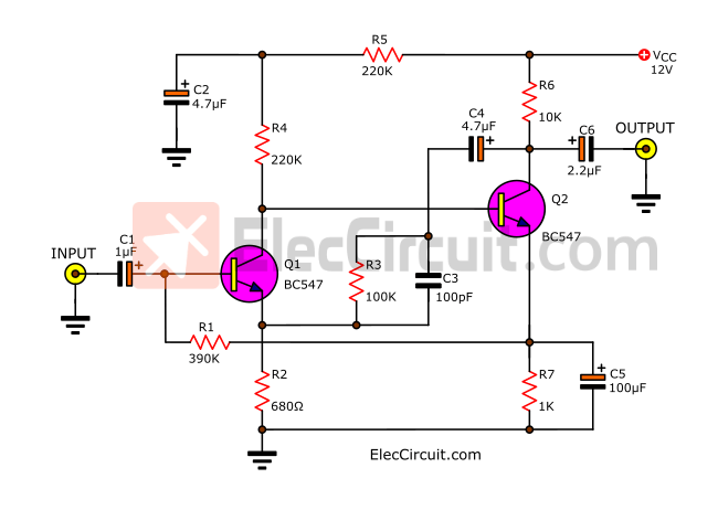
On the collector of Q2 will feedback signal to the emitter of Q1. To frequency response is improved.
And, at the same time, R1 will connect voltage from the emitter of Q2 to bias Q1.
The input signal into C1 to the amplifier by Q1, Q2. Then, there is the output signal at the collector of Q2 through capacitor-C6 to a power amplifier.
For the power supply of the circuit. We may use simple circuits as shown in block dash include Full wave rectifier D1, D2, and capacitor filter C7.
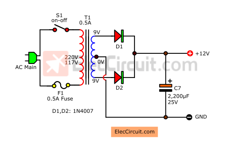
But someone who wants a high-quality power supply should use a 12V DC regulator.
The Shopping list
Q1-Q2: BC548, BC547, BC549_45V 100mA NPN Transistor
0.25W Resistors, tolerance: 5%
R1: 390K
R2: 680 ohms
R3: 100K
R4, R5: 220K
R6: 10K
R7: 1K
Electrolytic Capacitors
C1: 1uF 50V
C2,C4: 4.7uF 16V
C7: 1,000uF 25V
C3: 100pF 50V Ceramic capacitor
How to builds
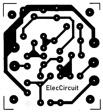
This circuit is easy and uses a few parts. So, you can build it on the universal PCB. However, some want to make it on the normal PCB. See an actual-size of the Single-sided Copper PCB layout below.
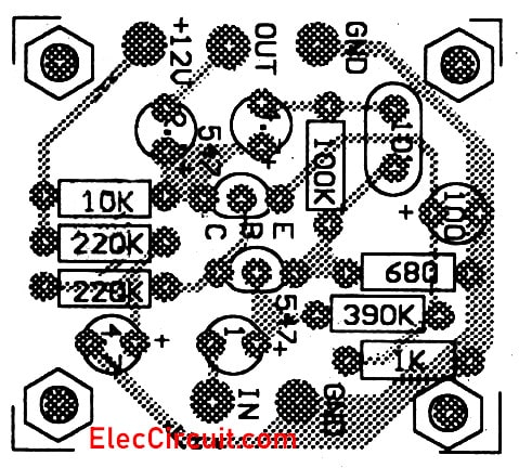
And see the components layout of this project.
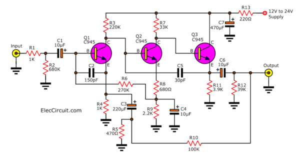
Dynamic Microphone Preamplifier using 3 transistor
You can see the project Dynamic Microphone Preamplifier using C945 transistor 2 vertion and easy to build with pcb layout see below.
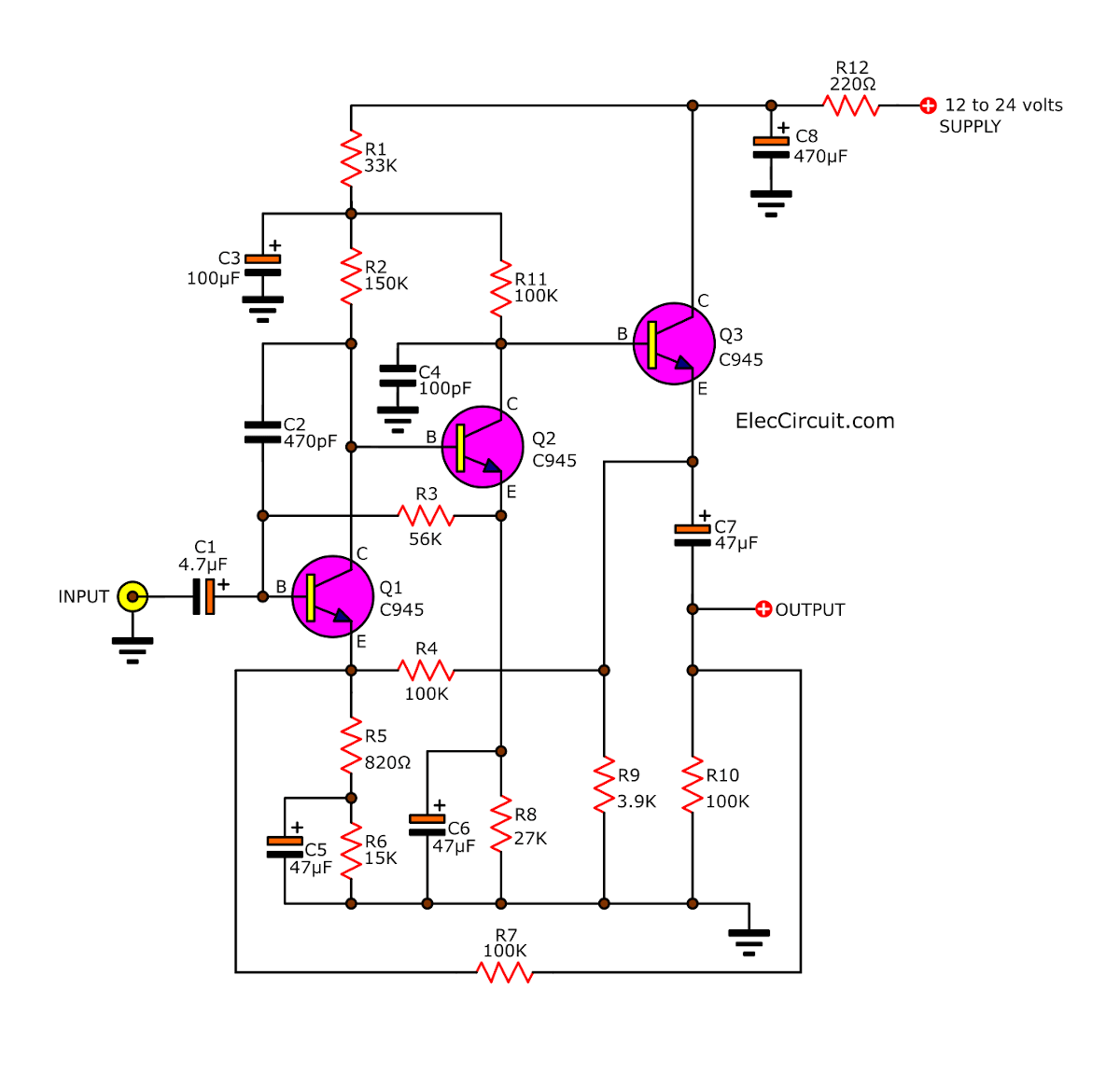
Here is a Circuit diagram of Pre MIC – 3 Transistors on Mono
Shopping list
- Q1-Q3: 2SC945, 2C1815, 2SC828, 45V 100mA NPN Transistor
0.25W Resistors, tolerance
How to build
This circuit is easy. You may make it on the universal PCB or Perforated PC board. However, some want to make a PCB see in the image below.
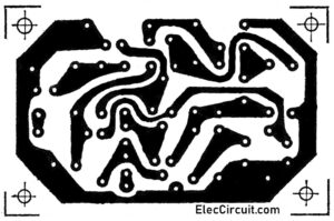
The Actual-size of Single-sided Copper PCB layout
Then see components layout here
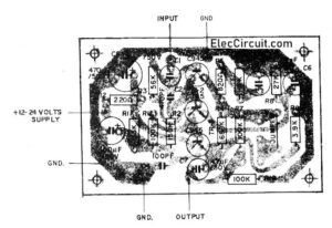
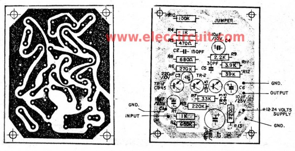
Are you clear view? See the components and wiring layout on PCB. below
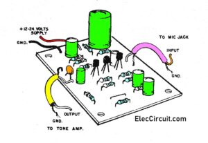
Not only that
Recommended: Low impedance input Preamplifier & Speaker Microphone
2nd circuit: 3 Transistor Dynamic Microphone Preamplifier
Read also:
- Simple condenser Mic Preamplifier circuit
- 9 Tone control Stereo Preamplifier circuit with PCB
- Flyback transformer tester circuit using 2SC828
Pre MIC mono using 2 Transistor C945
This is low noise microphone preamplifier circuit, by 2 Transistor mono part name C945 or C828 or 2SC829 or C458.
The supply volt is 12V – 24V. Easy to build and low cost.
I have an old microphone,I want to make play with common amplifier. It does not sound much. Must to use pre amp before.I search a lot of circuits, see this circuits it very well for me,low cost, use transistor.
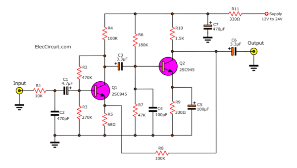
Circuit of Pre MIC mono by 2 Transistor C945
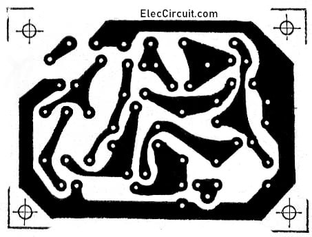
PCB of Pre MIC mono by 2 Transistor C945
Related Circuits
- 4 types of Preamplifier circuits
- 3 Low noise Microphone Preamplifier using ICs
- Simple dynamic and electret condenser microphone preamp circuit

I love electronics. I have been learning about them through creating simple electronic circuits or small projects. And now I am also having my children do the same. Nevertheless, I hope you found the experiences we shared on this site useful and fulfilling.



Verry good but how can i use c945 in an emetteur fm?
This circuit what I look for very useful for me,Thanks
how i can made radio with this circuits
Hi,Justinien
Thanks for your feedback.
Please use 2SC1815 = 2SC828 = 2SC945
Hi,Dwi Sugiarto
Thanks for your feedback.
Hi,midio
Thanks for your feedback.
No, You cannot this is not radio circuit.
But can i use us transmitter
this circuit is verry good, thanks for your post.
how to make the output is stereo?
Hello and thanks for this information, Id like to build the first circuit on this page, I’m having a problem reading “PCB of Pre MIC – 3 Transister (C945) mono” I cant see a clear guide… It is obscured by the black ink, please…. pretty please change the photo…. or… could you email me a copy of it?
i need completereport for this
Hello anbarasan,
I am happy. You like them. But now I do not have a full report for you. I am sorry.
Hi am a musician from Ireland. I love receing your circuits in my email.
About this Mic circuit, can it amplify a Piezo pickup or a very weak single coil pickup with very little winding.. I would be delighted if you can reply, pthank you
By the way, there is also a mistake in the overlay for the 2 transistor circuit. One of the two 220K resistors you show on it is actually the 100 ohm resistor.
Also just noticed that you state in the shopping list that R4 and R5 are 220K whereas in the circuit there is no R4 but there are two R1s, a 390K base resistor for Q1 and a 100 ohm resistor in the supply rail. Is this 100 ohm resistor supposed to be 100 ohm or 220K, I think 100ohm is more likely and my modified circuit certainly works with it.
First, my children and I sincerely apologise for wasting your time. My daughter has already fixed it. Thank you.
After fiddling with Q2 collector load I have found that 680ohm gives about the best symmetrical clipping, this does reduce the gain to about 37 db but pushes the bandwidth out to about 65 Khz.
Thank you for sharing this experience with us. My daughter will try out this circuit, just as you’ve shared. I hope you will share other experiences with us again. Thank you.