If you want to create the 100 watt OCL audio amplifier circuit. I have many circuits for you, transistors, and ICs.
Now using IC is a better choice. I want you to consider this circuit.

It uses the STK4231 chip to create a simple, small, without adjusting, and economical.
How it works
The STK4231 is a Hybrid IC of Sanyo, in the family of STK4201II. It can provide a high power output of 100 watts per channel.
And When connected to the bridge adapter. The its output altitude up to about 400 watts (It’s incredible).
The feature
It has main feature.
- Built-in muting circuit to cut off various kinds of pop noise.
- Greatly reduced heat sink-due to case temperature 125 degrees Celsius.
- Excellent cost performance.
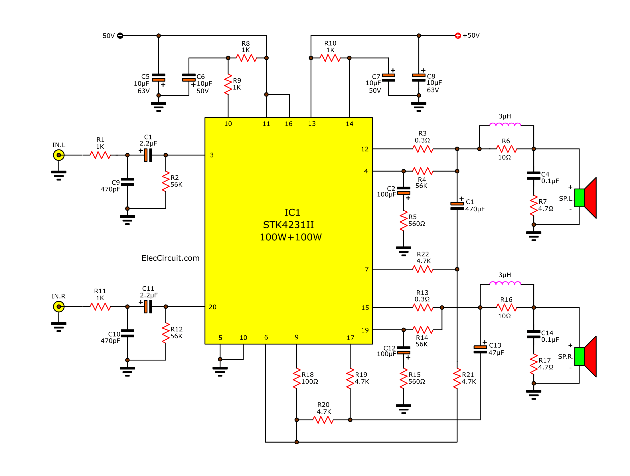
As this circuit, we can design the OCL amplifier 100 watts each channel. You will see that, this circuit consists of only a few external components.
Some detail may help you easy.
- The capacitor C9, C10 is used to reduce noise at high frequencies.
- Both C1 and C11 are the input coupling capacitors.
- The C2, C12 is defined for low-frequency cut-off point.
Which we can calculate from the formula :
F=1/6.28 C2xR5
Note:
- Both capacitor C2, C12 is defined gain ratio at low frequency. But they must do not over high.
Because, while open this circuit. It will be has a noise “thub…b.b.b” out to your speaker.
2. And both C3 and C13 are the boost trapping capacitors. If this value is too low. It will make more distortion at low frequency.
Then, both C5 and C8 capacitors reduce oscillation. Which, it will reduce the impedance of the power supply circuit to suit the use of IC.
Setting the gain ratio of the circuit.
It is defined by R5 = 560 and R4 = 56K. They will be total gain is VG = 40dB.
If you want to change the rate of expansion, it should change the R5.
Change idle current is defied by R21 and R22 resistors.
Hey! Oh… Is it too large circuit for you, Right?
Look below: You may like it.
Caution! This project needs to use the speaker protection circuit. Otherwise, your speaker may be damaged.
The power supply circuit
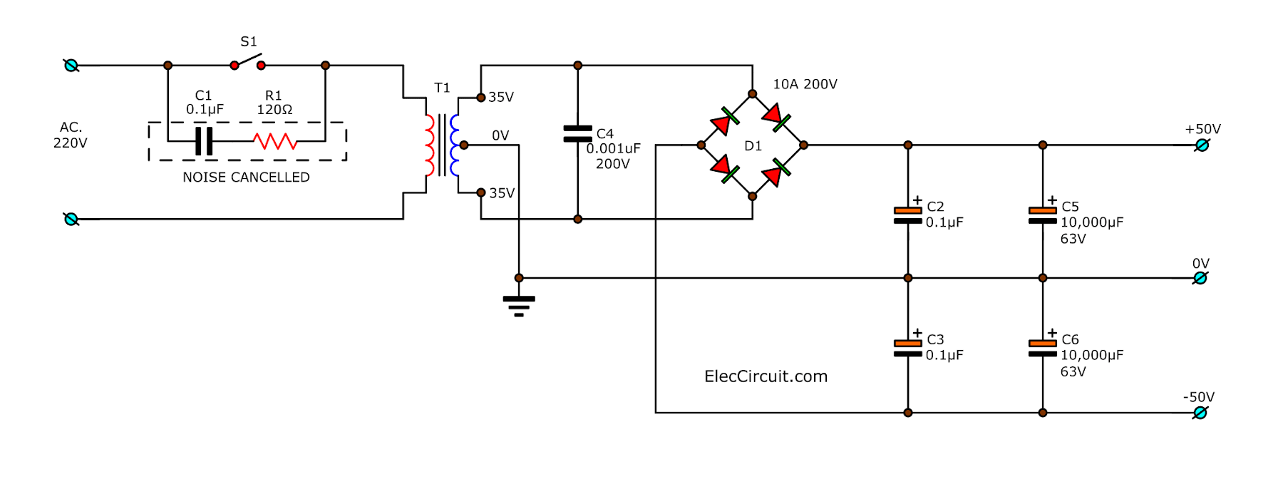
In this circuit requires the dual power supply circuit (positive – negative 50V and current is 5 Amps.
See the circuit below.

How to build
It’s very easy to build, even if you are a beginner. It is important to place the devices correctly follow the circuit diagram.
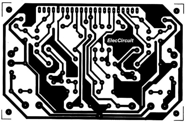
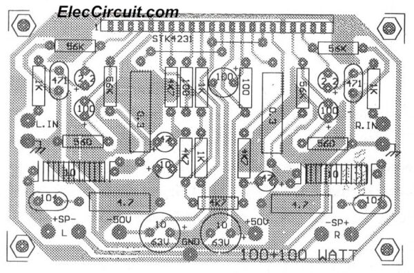
In this figure is PCB and putting position the parts.
Here is Copper PCB Layout
Then see components layout.
Shopping list
25W Resistors, tolerance: 5%
R1, R4: 470K
R8: 100Ω
Ceramic Capacitors
C9, C10: 470pF 50V
MKT (Metallized Polyester Film Capacitor)
C4, C14: 0.1µF 63V
Electrolytic Capacitors
C1,C11: 2.2µF 25V
C2, C12: 100µF 25V
C3, C13: 47µF 25V
C5, C8: 10µF 63V
C6, C7: 100µF 50V
Semiconductors and others:
IC1: STK4231II 2-Channel 100W min AF Power MODULE
L1: 3uH inductor
Note:
The IC STK4231II should be installed with the big heat sink.
Thanks a lot: Prakit Book
You may like these circuit, too.
Other circuits are recommended
More Audio Amplifiers with PCBGET UPDATE VIA EMAIL
I always try to make Electronics Learning Easy.
Related Posts

I love electronics. I have been learning about them through creating simple electronic circuits or small projects. And now I am also having my children do the same. Nevertheless, I hope you found the experiences we shared on this site useful and fulfilling.



Please share me the PCB Circuit layout for the STK4321 MK 2 as i will love to try the Making of PCB STK4321 MK2 ..
RGDS
Rakesh Sharma
Call + 91 9762089423.
I need two pcb of stk4231 .can you please arrange it.
Sir
I need two numbers of stk4231pcb.
Can u print any pcb broad
Sir, I need a 4231-II stk board without ic, genuine quality, I have a stk 4231-II ic. Can u arrange it.
in this circuit how to use 5.1 hometheater used,with stk4231 ic and 8 inch subwoober,and with 100 watts only other speaker or how to use wstts.
STK4231 original ic how much price?
Hi,Bala
I am sorry,I don’t know its prices now.
Thanks
stk 4231 ic
avialable in kerala?
price is app 400 inr/Rs
350/TK in Bangladesh
Hi,Mehedi
Thank your feedback.
Or you can look for it in amazon.com
hai friends iam raju from yuvaraj Electronics.my bisnes stk amplifiers i want stk 4231-11 components pcb boards please any infarmation
Dear,for assembling STK-4231-11,can i use the same pcb configuration used forSTK4141-11?Because i had a stk 4141 circuit working with 30V/5Amps Dc Dual supply,that ic got defective.it may be replaced.STK 4231,is it available at kolkatta market?
Thanks
Where availabel at mumbai stk 4231II ic and all type high waatt ics please give me address my self prashant
this ic (stk4231II) IS 200000 rials in iran.
thanks for your great circuit.
Hi Mohammad,
Thanks for your feedback.
It is old IC that good sound for me.
very nice i want to one 1000 watts power amp board good sound your me.
Hi thanigaimani,
Thanks for your feedback.
Now I not have 1000 watts for ICs, I have mosfet model: https://www.eleccircuit.com/300-watt-1200-watt-mosfet-amplifier-for-professionals-only/
where can i get panasonic sa-vk800 multi amp system STK 470-090 IC
hi. why pin 16 is connected to -50v in pcb and top silk but in schematic pin 16 of stk isn’t connected to -50v? and another question that why do you use 100uF capacitor except 10uF(C7) in top silk?please help.
please suggest any 5.1 audio for 100watts
Hi momename
please help me faster.I bought it’s components and I dont know
what to do?I need your help.
Hi momename
i made this circuit according to the top silk
that you had put in this part for stk.
now I want to say if others want to make this circuit;
please follow the top silk information.
when i wanted to start this circuit;suddenly I SHOCKED
OF IT’S VOICE. IT WAS VERY EXCELLENT.I suggest you to
make this circuit and enjoy of it. thank you very much momename for your great amplifier circuit.
Hi david,
Thanks for your feedback.
where shall i get 4231 ic build amplifiers in chennai market or inside tamilnadu
Should pin 16 shouldnbe connected or left opened….?
And i am following the schematic diagram i.e. the first diagram..so is it correct?
is stk 4321 mk II available in kolkata
I made the circuit but its not working…i tried with schematic , top silk and the bottom layer but the resistor R10 is getting burnt and the ic is getting heated…please help as soon as possible…!
The value specified for R10 is 1 killo ohms i also tried with 10killo ohms…that also is getting burnt…please help
hi sir, can u pl arrange pcb
how many current in stk4231 audio amplifier max.
STK 4231 redi avelebal he to context mi hame chahiye holsel my cnntect no 09427388905
you will get all stk ics at ebay.com
Bangladash market price only $3.00. Thanks.
Sir i am desired used this ic to subwoofer for 5.1 system pls said transformer rating alsow which ic used to other 5 channel for 5.1 system
Hi, can you share the circuit diagram for power supply?
[email protected]
sir gud pm
value of resistors is it 1/4 watt or 1/8 watt and for capacitors how many volts do i use
tnx and god bless
hello,
what is the speakers specs?
the input in voltage is 50+ 50- , but what is the input in Amps?
What is the size or watts of R3,R13,R7,17?
how many 8″ speakers may connected in stk 4141
what abt no.8 pin (Mute)….? how to open this point…by giving +5V supply or not..???
now i want to adjust bass, volume but i don’t know how to do that , Could you recommend me?
I want to make a 50+50W amplifire please give me a link there is details
Hi.I live in London England.Is it possible to buy the Pcb and components including speaker protection circuit for TDA2030 100w stereo amplifier with PCB.If so How mutch in £ wiil it cost.Thanks Bernie
Hello Bernard de Grasse,
Thanks for your visit. How are you?
You mean this circuit, right?
https://www.eleccircuit.com/speaker-protection-circuit/
I am sorry that cannot sell a PCB and Components to you.
I am very busy.
But I believe you can build your own PCBs and purchase components online.
Have a great day.
Apichet
Hello, I apologize for my bad English. I would like to point out that pins 5 and 10 have been superimposed in the STK4231 diagram. However, I built following the diagram and the L channel is perfect but the R channel produces 50 volts by burning the speaker and I don’t understand why …
What about pin 8 for muting not explained
I have a Sony Active Superbass SA-W441. Is it possible to use this as a stand alone Stereo amplifier ? It has the same Chip as the one used here.
Chip
pin number 5 and 18 connected… not 5 with 10 . you mentioned pin number 5 with 10 in figure ….. please correct the digram 5 with 18
..