If you are looking for 5V DC power supply for the digital circuit. But you have a 12V source, battery. I will show you, 12V to 5V converter step down regulator.
In many ways for using, it depends on parts you have and other suitability.
How to Choose a 5V converter
We should use a suitable circuit. How? The saving is the best. I use these guidelines.
- Save money—if I have it in my store it is so good. Also, save time to buy, not a long wait.
- Easy to build—simple and worked circuits are always good.
- Small size—some project has a Limited space.
Look at the load first!
Suppose that the load uses a current about 30mA. You should use the 5V converter at 60mA. It is enough for this case. When the current is small, it is small and easy to build. Also, save energy.
You should not use a large 1A current source circuit. It is like to ride an elephant to catch a grasshopper. Which it is wasteful and unnecessary.

For example circuits
- 3A current output—if you have the load that uses a current of more than 2A. For example, a digital camera, GPS, Raspberry Pi, Arduino and more.
- Lower than 50mA—Small circuit, for example, CMOS digital
- How to convert 12VDC to 5VDC 1A
- 12V to 5V 2A converter circuit
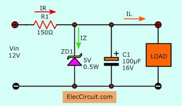
5V Zener diode Regulator—Lower 50mA
Some circuits draw the current from 20mA to 50mA (0.05A) only. You can a Zener diode voltage regulator circuit.
The Zener diode keeps a fixed voltage, 5V. It needs a resistor to limit the current to it and load.
How to calculate the device
To power it from a 12V source. You look at in the circuit again. There is three current.
- IZ = Maximum the Zener diode current
- IR = The Current through R1
- IL = Maximum the load current
IR is a constant at all time. Even IL will change from 0 mA to planned maximum value (50mA). IZ need to change to keep the voltage across the output is 5V.
First, use 5V Zener diode because we need 5V, VZ. Then, IR is about IL, 50mA.
R1 = (Vin – VZ)/ IR
= (12V – 5V)/ 50mA
= 140 ohms
or about 150 ohms.
PR is Power of R1.
PR = VR x IR
= 7V x 50mA
= 0.35 watts or use 0.5 watts.
But we forget, a power of the Zener diode, PZ
PZ = VZ x IZ
Note: IZ is about IR, 50mA.
PZ = 5V x 50mA
PZ = 0.25 watts
So we use 5V 0.5W Zener diode.
Also, C1 is a filter capacitor to smooth DC voltage.
100mA 5V converter circuit
In the digital circuits that have many parts. They may use the current more than 100mA but lower than 300mA.
We can use many circuits. In the previous circuit, it has a low current. If you want 100mA. You need use a low resistance (R1) and higher watts of the Zener.
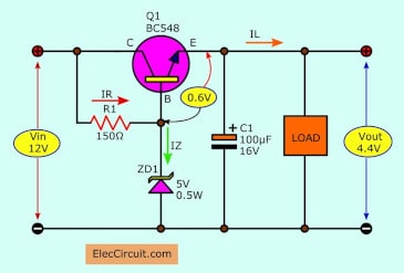
It is a better idea. If you add a transistor in the circuit. It will increase a higher current more. But the output voltage is 4.4V only. Because of some voltage drop across BE of transistor Q1, 0.6V.
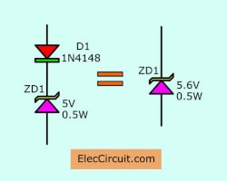
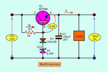
We need to change the Zener diode is 5.6V. If you don’t have it. You can add a diode and the Zener in series. You can get them like 5.6V Zener diode.
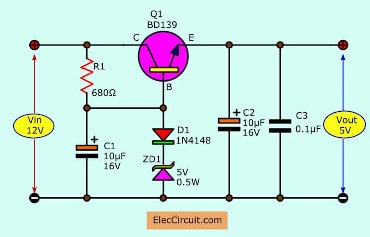
Since a transistor is good to increase the current. So, we can change R1 to be 1K as circuit below. To reduce a bias current Zener diode and the Base of Q1.
200mA, 5V Regulator
5V transistor series voltage regulator
If you use 2N2222 instead of BC548. It can use 200mA @ load. Because 2N2222 has a current collector (Ic) of about 0.8A in a datasheet. But in real using it can use max 0.5A only.
500mA, 5V regulator from 12V
500mA, 5V transistor, and Zener voltage regulator
If you need to use with 300mA to 500mA load. You should change the transistor is BD139.
It has Ic about 2A max in spec. But I can get it about 0.5A only. While it is working. It may be warm. So often perform better with a heat sink.
C1, C2 capacitors are used to reduce the ripple output. And C3 will reduce a spike voltage.
How to convert 12VDC to 5VDC 1A
Many friends want to convert 12VDC to 5VDC at 1A. It is the popular rate in the most circuits.
I have two choices to choose from. It depends on The suitability of your parts and time.
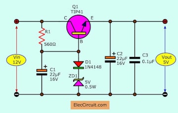
First, 5V 1A transistor Regulator. It is similar to the above circuits.
I use TIP41 power transistor. Because it can get 4A max in spec. But in real using it can give me about 2A max only. Also, its body is TO-220 so easy to use with any size heatsink.
Before I like this circuit. If I have all the components in my store. I will make it first.
But lately, I like to use this component, 7805 Regulator.
Second, 7805 Regulator popular.
This is so easy, faster than other. Because its body is the same as TIP41, without Zener diode and a bias resistor.
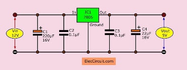
12V to 5V converter 1A using 7805
Also, it has low ripple output about 10mV, with the electrolytic capacitors(C1, C4) on the input and output. And both filter capacitor, C2, C3 to reduce the spike voltage.
Note: 7805 pinout
Since it is the linear regulator. So while it is working. There is the voltage across input and output of IC1 about 7V.
When full load has a current of 1A. So the output power is about 7 watts. It is hot. We should mount it on enough heatsink.
12V to 5V converter 1.5A output
Sometimes we need an output current about 1.5A. We have 3 ways to do.
- Connecting 7805 in parallel
- 12V battery to 5V 1.5A DC converter
- Higher current transistor for 7805 Regulator
- 2A transistor Regulator
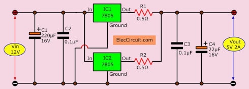
Connecting 7805 in parallel
If we connect 7805 in parallel. It makes higher current more. This is suitable for who carry up or do not have any power transistors.
But it is not good for a long time. You can try it!
Both IC-7805 should be exactly the same.
12V battery to 5V 1.5A DC converter
If we need to use 12V to 5V voltage regulator. This is the 5V 1500mA DC regulator circuit.
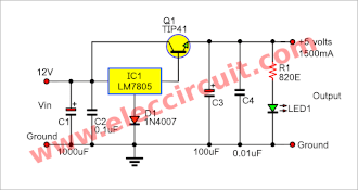
Which is a simple circuit using IC-7805, to the fixed regulator 5 volts and TIP41-NPN power transistor to increase current up to 2A.
Example experiment
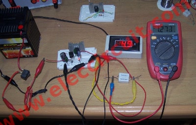
I use the 7805 power supply with the 12V battery. To reduce the constant voltage of 5 volts.
I try to use the load is 4.7 ohms 5W resistors. As principles, it will use the current about 5V/4.7ohms = 1A.
I measure the current of about 0.7A and the voltage drop is 4.9V, but it is still usable. As Figure 1
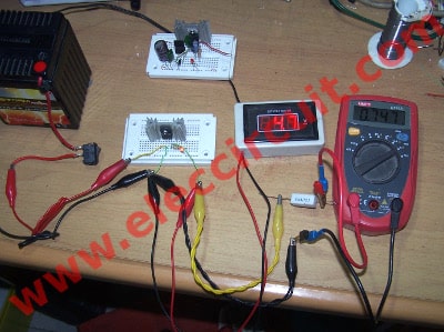
Testing pure IC-7805 not over 1A current.
It requires a transistor to increase the output current up.
I use the TIP41 transistor. In principle, it can supply the current about 2A. Which it is enough to use.
In the circuit diagram.
Simplest 5V 1.5A regulator circuit diagram
Then, I test the circuit with about the load, 2.4 ohms resistor. Next, measure current approximately 1.3A, and the voltage drop is 4.9V. It can be used as we want.
Testing with high current load
Keep reading: Four Small 5-volts DC Regulator Circuits »
I put a Diode-1N4007 voltage to offset the loss of the transistor between pin BE.
We insert LED1 to indicated power on of this circuit and a series resistor-R1 is used to limits current to a safe value.
C1, C3 is filtered capacitors to smooth dc current input and output sequence.
C2, C4 is noise filter spark current.
While Q1 is working it will very hot so we must mount it with a large heatsink.
Note: It has cons. If it short circuit. IC-7805 may be damaged.
Higher current transistor for 7805 Regulator
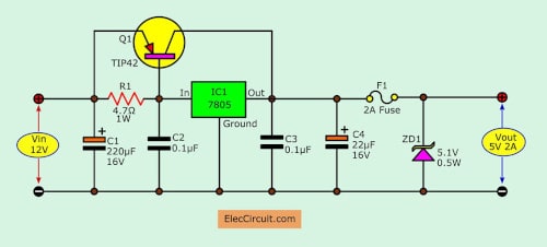
If you want the current more than 1A using 7805 in better than 2 circuits above.
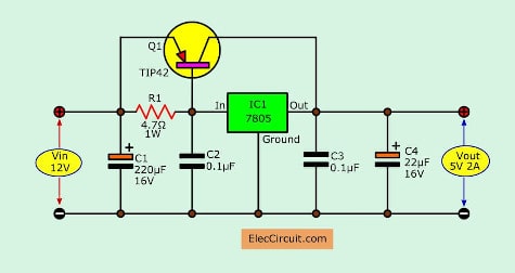
It needs helping from a power PNP transistor, with circuit below.
12V to 5V 2A converter circuit diagram
The high current will flow through the power transistor Q1, TIP42. While 7805 gets lower current. Because R1 reduces this current down.
So 7805 keeps a fixed regulated voltage, 5V only. It works well without the heatsink.
While Q1 is working. It is so hot. We need to mount it with enough heatsink.
If you have the ready parts. You can use this circuit for a long time.
Then, if you want 3A current. It is easy just you use MJ2955 instead of TIP42.
Although this circuit can be used well. But it still has disadvantages.
When a short circuit, the power transistor may be damaged.
Look at below.
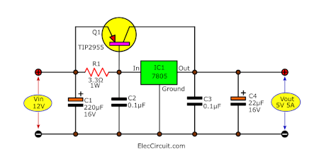
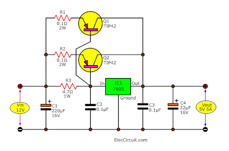
12V to 5V 5A converter
If you want 5V 5A output. You can change the previous circuit. Use TIP2955 instead of TIP42.
It can drive current up to 5A.
Or If you have another one, TIP42. You can add it in parallel. The output current will be up to 5A, too.
3A current output, 5V converter
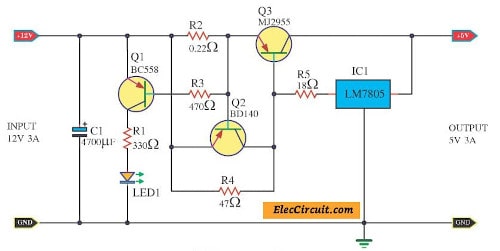
This is 12v to 5v converter step down Regulator at 3A load.
12v to 5v converter step down Regulator
The digital camera can take pictures and videos as well. But it has a disadvantage is not long the battery runs out. When using outdoor. We needed to often recharge the battery. It is quite a waste of time.
If buying additional spare batteries. It is expensive and still often to change as the same.
Its side has a slot for plugging DC 5V adapter, 2A current. If we modify 12V lead-acid battery to reduce a voltage down to 5 volts. It is so good idea.
Because this battery is cheaper and long time using. For example, 12V 10Ah battery you can take the camera for 5 hours.
How it works
We have many ways to do. But I will show you this circuit below. I like a linear circuit than a switching mode circuit.
There are many components in the circuit. As above this circuit can power up to 3A current with an increasing current of Q3-MJ2955. Also, it has many parts interesting.
When the load is overload or short circuit. Then, a voltage is across R2 about 0.6V. So, Q2 gets a bias voltage, it works. After that VBE of Q3 is low, Q3 works lower until stop.
While Q1 works to connect current through LED1. It indicates now overload.
Component list of 12v to 5v voltage regulator
IC1: LM7805, 5V dc regulator IC
Q1: BC558, 0.4A 40V transistor
Q2: BD140, 1.5A 30V PNP transistor
Q3: MJ2955 or TIP2955, 4A 50V PNP power transistor
C1: 4,700uF 25V, Electrolytic
LED1: LED any color as you like
Resistors
R1: 330 ohms 0.25W
R2: 0.22 ohms 5W
R3: 470 ohms 0.5W
R4: 47 ohms 1W
R5: 18 ohms 1W
Heatsink, wires and more etc.
Application
I have old GPS, usually, I use it in my car. We need to have DC to DC converter circuit that can reduce voltage 12V to 5V at current more than 2A.
Which circuit diagram can make this.
I like it that need to buy some parts since I have also in my stores.
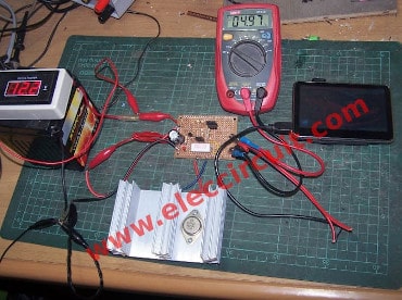
As Figure 2 I assemble them on universal board
Also, See others in an easier circuit. 3A 5V regulator using LM350
Simple 5V overvoltage protection
In normally you can use the above circuit. Because it is simple and inexpensive.
You just add Fuse-F1 to protect overload more than 2A. Also, if the circuit powers high voltage more than 5.1V. It has too many currents through ZD1 and D1 as overcurrent. So the fuse will burn suddenly.
12V to 5V converter at 2A using 7805 and transistor with over voltage protection
5V 2A power supply using 78S05
Another way, My friend wants a 5V 2A power supply circuit. In model to be simple, use little equipment, build easy.
Then, I choose this circuit for him.
Why is it? It uses pillar equipment, a positive voltage regulator 5V / 2A in TO220, 78S05. And few parts see in a circuit, is high-quality and low noise.
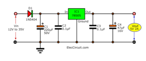
The circuit will work without the extra components, but for reverse polarity protection, a 1N5402 diode is provided at the input, extra smoothing being provided by C1-220uF 50V.
The output stage includes C2-47uF 25V for extra filtering.
It is better if you use a switching mode regulator circuit using a 34063 chip: 5V 2A buck converter
Download This
All full-size images of this post are in this Ebook: Elec Circuit vol. 1 below. Please support me. 🙂
Also 5V DC adapter
- Microprocessor dc regulator supply 5V 3A by LM323K
- 5V 3A switching power supply by LM2576
- LM2673 -5V 3A Switching Voltage Regulator
- Top Linear power supply regulator 5V 5A with 7812 and LM723

I love electronics. I have been learning about them through creating simple electronic circuits or small projects. And now I am also having my children do the same. Nevertheless, I hope you found the experiences we shared on this site useful and fulfilling.

12V to 5V 3A DC converter step down Regulator shows r2 as 0.22 ohm resistor. what should it be?
I had a typo on my previous request. On circuit 12V to 5V 3A DC converter step down Regulator, shows r1 as 0.22 ohms, what is the correct value?
I would like of schematic diagram circuit of voltage regulador that can input with voltage between 6V and 13V and has constant 5V output for 1A
Q3 error
Hi, Petro_Mustafa
Thanks for feedback.
what wattage are the resisters? at 500ma R5 melted. For bd140 I used nte242, for bc556 I used nte232 for mj2955 I used nte332. I know nte332 needs a big heat sink …what about the rest?
As an added bonus if you thermally couple the transistor to the regulator (close together on the same heatsink with thermal grease and mica insulator) the transistor will be protected from overheating. If the transistor overheats it also heats up the regulator, and the regulator has built in thermal regulation. When the regulator shuts down, it also shuts down the transistor.
nice, what would be the voltage in 4700 microfarad capacitor?
how many resistance required to convert 60 v dc to 50 v dc
Hi, reyn
Thanks for your feedback.
You can use the Capacitor’s voltage more than 25V.
Hi, dharmendra singh.
Thanks for your feedback.
I am not clear your question.
This circuit can reduce voltage 60v to 50v.
https://www.eleccircuit.com/0-60-volt-dc-variable-power-supply-using-lm317lm337/
It is good regulator but maximum current is 1.5A only.
How to convert 12v 7.2ah battery to 5v 15A output.?
can i parallel the transistor so it gives much current output?
please do reply
How to convert
12 dc to 5v dc 1A
Please help me
[email protected]
Hi Mithlesh sahu,
Please in text again. I just add the circuit as you want. 12V to 5V 1A.
Hi everyone,
I implemented this Circuit on a breadboad with the aim of using it to charge my android phone via two input sources. With
(1)Three small DIY Solar Panels that i connected in series and it gave about 13V-10V
(2)Six 18650 Li-on cells that i harvested from my old laptop battery,i also conected them in series and parallel to give out about 12V-10V
Now my problem is that…each time i connect the usb head to my phone,it gives out the 5V BUT THE CURRENT drops rapidly from 870mA to 0mA…instead of increasing gradually from 870mA to 1000mA as my normal Phone charger does,please what could be the cause and how can i make it retain current to charge my android phone the same way its normal charger does?
PS: It’s not only with this circuit that I’ve observed this,I tried with several other Linear Voltage Regulators like the LM317T and still get the usual 5V but the current drops rapidly from 870mA to OmA. Please i need an urgent reply ([email protected]). Thanks in advance
24v to 12v 10amp please help me
24v to 12v 10amp dc to dc please help me
Sir i try this circuit I tested on 12 volt 8 amp batter but at the out side current show 10.56 instead of 5 volts. Sir can u tell me how to reduce current at least 5 volt. Amp are on my demand but current is very high. Please help me.
How to decrease ampere 5ampere to 1ampere.
Plz help me…..
12v to 3amp fir el wire stripe?
How to convert 24V to 12v using opto-isolation please help me.
Why is the current limited to 2amps. The tip41 transistor is capable of 6amps per spec?
why is it that i get a much higher voltage output is there something wrong i get 14v on the output
Noob questions,
If i used 12v 6A input it still 3A output?
This circuit output is 5v/300mA only.
Why resistor 18ohm is hot to touch?
250v to 5v how to convert
Can i replace voltage regulator to ka7805?anyone know?
Hi Zul,
Yes, you can. Since the IC-7805 can tolerate about 25V input. But I think you should max 18V because it not heat. If you use over voltage you need to change R5-18 ohms to 22 ohms or more as rating voltage input.
Thank you
led products
i need a laser charger for my quadcopter..it comprises a 30c battery with 12v o/p.
it looks very difficult to buy.need help ,where to buy? abubakhar9088agmail.COM
Thank you for explaining details from 12 vdc to 5 vdc charging mobile phone.
I’m riding exercise cycle the come with 6 vdc battery as backup power. I like to add USB to charge my tablet or mobile phone during my exercise. How can I get from 6.2 Vdc to 5 VDC at 2 amp fast charging? My tablet and mobile phone is designed for fast charging. Can you give detail in drawing to make one? Thank you
Hi, John
Thank you for the great question. But I never learn a fast charging for a new mobile.
Anyways I think you can try the low dropout voltage regulator. 6V to 5V step-down.
Like this: https://www.eleccircuit.com/low-dropout-5v-regulator-using-lm317/
If you have news please share me.
I have recumbent exercise bike CR52. It has small 6 volt battery. Testing battery is 6.67V as full charge. I want to reduce to 5V to charge my iPad. I have USB socket ready but not sure how to step down 5V with 2A. I’m not good at electronics math figures. I know how to read schematic of electronic components. I have plenty leftover old automotive 5V charger devices for 12V but very low amp current. I would like to get help of drawing schematic layout to work from 6V to stabilize 5V – 1.5 to 2a if possible.
Let me know Thank you,
John
Hello John Hungerford,
Thanks for your question. Let me show you an opinion. Which if it goes wrong Please forgive me.
Of course, using a switching battery charging circuit is of good quality. But I don’t know how its circuit is?
The easiest way is to use two diodes in series to reduce the voltage down. From 6.6V battery is reduced to 5.4V (6.6V-1.2V) You may use 1N5402 (3A 200V Diode).
Or you may use a low drop voltage regulator circuit 6V to 5V.
I want to experiment with creating this circuit for you (if I’m free).
Thanks
Apichet
It’s perfectly working tip42 transitor using circuit and also need small changes in your circuit in tha load side 2.5 ohms resistor it’s for constant Amps output
can you please tell my if i have 10 amps 12 volt dc and transform it to 4.4 volts dc how meany amps would i have can you email my thank you
Are you have idea for battery 12vdc into. -12 0 +12vdc. ?
Hi Durai,
Thanks for visiting.
I’m not sure. Is this circuit best for you.
https://www.eleccircuit.com/dc-converter-5-volt-to-12-volts-or-high-volt-than-12-volts/
Or See: https://www.eleccircuit.com/dc-converters/
I need 5v 5A low noise for audio in my car. Can you suggest a good solution.
Hello Lak
Please look at this: https://www.eleccircuit.com/12v-to-5v-converter-step-down-3a-regulator/#12V_to_5V_5A_converter
It may help you. If there is progress. Please don’t forget to share with me.
Hello,
Is this 12v to 5v 5A converter linear or switched? Does it work with 14V input? What is the minimum input voltage of it?
Thanks
Hello Imre,
Thanks for your visit. How are you?
I’m happy that you are interested in this circuit.
It is a linear circuit. Easy to build if you have parts it is good ideas.
Yes, it works with 14V input. I think the minimum input is 7V to 8V.
If you try this circuit please do not forget to share it with me.
Thanks
Apichet
Hai… Can i download file Pdf dor this schema?
Hello, Red Fox
You can download the circuit full size. Click mouse right then click save as image.
Hello ElectCircuit, this is tmy first time if visiting your site and I’m really impressed by the the contents of your site , your style is good .
Hello Caleb,
Thanks for your visit. I am happy that read your text. I will keep this work for everyone.
Thanks again
Apichet
Lot of options, what about a 12V to 5V converter, suitable for a 4-port powered USB 2.0 HUB?
I would like to create the circuit, with the relevant protection and precaution, to convert 12V DC input, in a 5V DC output suitable for a 4 port HUB. This particular HUB, always 2 port populated for a 800mA, with a spare two port that can be use for unkon device, for USB 2.0 standard can draw up to 500mA, each, for a total of 1.8A with all populated device.
Which is the best option, should I consider a circuit for a 3A so it will not heat so much up when everything it’s populated?
Thanks
Hello Andrea,
Thanks for your visit. Yes, we have a lot of choices or ways to do. 12V to 5V converter
3A putout is good for you. If your load wants 1.8A current.
Dear Apichet
Thank you for sharing.
About this circuit:
https://www.eleccircuit.com/wp-content/uploads/2014/04/Higher-current-transistor-for-7805-Regulator.jpg
If I replace IC 7805 with IC 7806, I will get 6V / 2A output, is that so?
Do I need to replace other components?
Thank you so much.
Hello Amdani Wijava,
Thanks for your visit to my site.
Yes, You can use 7806 instead of 7805 in this circuit.
Also, other components are the same.
I hope you are happy with this circuit.
Have a good new year.
Apichet
Thanks
Hi, Anil
Thanks, too.
what is the voltage for the 0.1uf capacitor?
Hello Steve Akenda,
Thanks for your visit. The voltage of the 0.1uF capacitor is 50V.
Please I need your helps about circuit mobile charger for samsung 5v/2A Fast charger If you have any idea send to me
Thanks
Hi
thanks a lot
i tried to make tip2955 circuit board
to charge mobile phone
using 12v battery
the current is too small when i connect it to mobile phone
but it reach to 4A when i load “fan”
i have read something about pre-load to charging batters
is it make any sense ?
and how to have Higher amps to charge mobile phone ?
please replay
thanks
Hi,
My kids try this: https://www.eleccircuit.com/experiment-with-parallel-transistors-for-more-current/
It can power a high current with these circuits. Four transistor is better than only one transistor to drive higher current.
Thanks
I was very enthusiastic visiting your site
HI, I ALREDY MAKE TH CIRCUIT Connecting 7805 in parallel
, but i don´t have 0.5ohms, resistors, only i have 1.0 ohms, what will happen if i make it whit this resitors??
The current will be reduced if a 1 ohm resistor is used. If you have multiple 1-ohm resistors, you may want to connect them in parallel first. This lowers its resistance to 0.5 ohms.
I hope my review helps you to learn more about electronic circuits.